GIS equipment test system and method
A test system and equipment technology, applied in the field of GIS equipment test, can solve the problems of deviation of the real situation, the contact between the static contact and the moving contact is different from the actual working condition, affecting the hot spot and the internal temperature value of the gas chamber, etc., so as to improve the efficiency. Effect
Active Publication Date: 2021-03-19
FOSHAN POWER SUPPLY BUREAU GUANGDONG POWER GRID
View PDF12 Cites 0 Cited by
- Summary
- Abstract
- Description
- Claims
- Application Information
AI Technical Summary
Problems solved by technology
Although this patent can simulate the contact state under different contact depths, contact materials and contact pressures, apply voltage and current to the dynamic and static contacts of the device during the test, and actually measure the contact resistance and contact point temperature under different contact states, but the patent A part of the moving contact and the static contact are located outside the housing. According to the theory of heat transfer, the natural heat convection of the gas has a great influence on the temperature inside the gas chamber and the hot spot. The structural design of this patent will seriously affect the nat
Method used
View moreImage
Smart ImageViewing Examples
Examples
 PUM
 Abstract
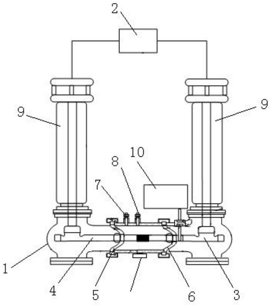
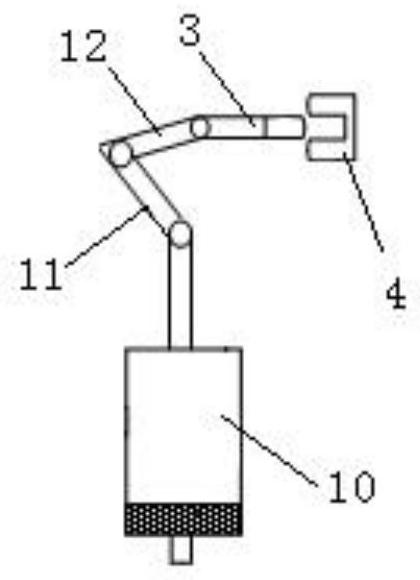
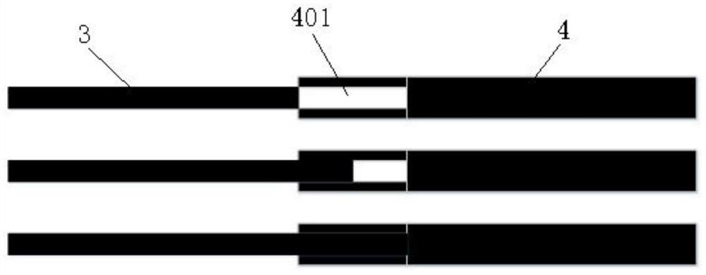
The invention relates to the technical field of GIS equipment tests, and discloses a GIS equipment test system, which comprises a shell, a current booster, a moving contact guide rod, a static contactguide rod, an operating mechanism, a first basin-type insulator and a second basin-type insulator; the static contact guide rod and the moving contact guide rod are arranged in the shell and are horizontally arranged in a straight line; one end, close to the static contact guide rod, of the moving contact guide rod is provided with an insertion groove for the static contact guide rod to be inserted, the positive electrode and the negative electrode of the current booster are electrically connected with the static contact guide rod and the moving contact guide rod respectively, and the operating mechanism is connected with the static contact guide rod to drive the static contact guide rod to move. The first basin-type insulator and the second basin-type insulator are both arranged in the shell and connected with the shell, the static contact guide rod is fixed to the center of the first basin-type insulator, the moving contact guide rod is movably arranged in the center of the second basin-type insulator in a penetrating mode, and through holes are formed in the first basin-type insulator and the second basin-type insulator. And a vibration detection device and a temperature detection device are arranged on the shell.
Description
technical field [0001] The invention relates to the technical field of GIS equipment testing, in particular to a GIS equipment testing system and method. Background technique [0002] Gas Insulated Switchgear (GIS) is more and more widely used in the power grid due to its small footprint and low maintenance workload. [0003] GIS is an important equipment in the power system, and its working reliability is of great significance to the safe operation of the system. The switch contact is a key component in GIS, and the local heating of the equipment due to the poor contact of the GIS contact is one of the main factors causing the failure of the GIS. According to the analysis results of GIS typical defects and accidents by Guangdong Power Grid Corporation, 29% of grid faults are caused by poor contact of GIS contacts, of which 11% are due to poor contact of main contacts, and 11% are caused by poor contact of shielding covers. Failures accounted for 18%. During long-term ope...
Claims
Login to View More Application Information
Patent Timeline
 IPC IPC(8): G01R31/00
CPCG01R31/00
Inventor 陈邦发王鹏洋陈道品张岳高轩谢志杨李恒真黄静王俊波
Owner FOSHAN POWER SUPPLY BUREAU GUANGDONG POWER GRID
- R&D Engineer
- R&D Manager
- IP Professional
- Industry Leading Data Capabilities
- Powerful AI technology
- Patent DNA Extraction
Learn More Browse by: Latest US Patents, China's latest patents, Technical Efficacy Thesaurus, Application Domain, Technology Topic, Popular Technical Reports.
© 2024 PatSnap. All rights reserved.Legal|Privacy policy|Modern Slavery Act Transparency Statement|Sitemap|About US| Contact US: help@patsnap.com


