Supercharge Your Innovation With Domain-Expert AI Agents!

An on-chip thermal regulation system and its control method

A control method and thermal adjustment technology, applied to auxiliary controllers with auxiliary heating devices, temperature control using electric methods, etc., can solve problems such as low energy utilization efficiency, and achieve high energy utilization efficiency, high integration, and The effect of improving utilization efficiency

Active Publication Date: 2021-12-31
HUAZHONG UNIV OF SCI & TECH
View PDF10 Cites 0 Cited by
  • Summary
  • Abstract
  • Description
  • Claims
  • Application Information

AI Technical Summary

Problems solved by technology

[0005] In view of the above defects or improvement needs of the prior art, the present invention provides an on-chip thermal adjustment and driving method, which aims to solve the technical problem of low energy utilization efficiency in the prior art

Method used


Image

  • An on-chip thermal regulation system and its control method
  • An on-chip thermal regulation system and its control method
  • An on-chip thermal regulation system and its control method

Examples


Embodiment 1

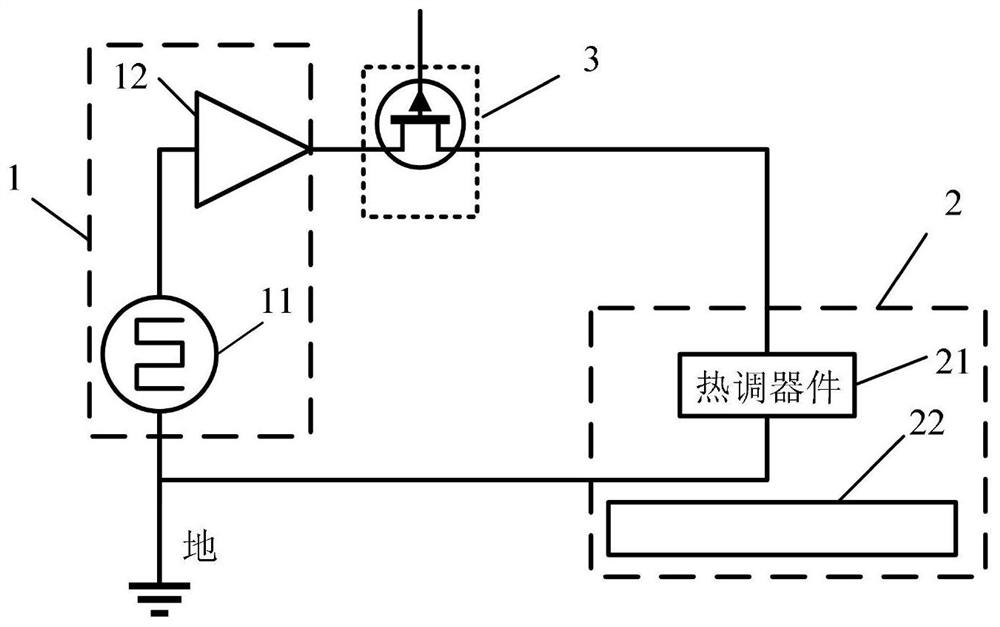
[0039]An on-chip thermal regulation system such as Figure 4 As shown, it includes: an electric chip 1, an optical chip 2 and a switch tube 3; the optical chip 2 includes a thermal adjustment device 21 and an optical device 22 (specifically an optical waveguide) to be heated placed on one side of the thermal adjustment device 21, and the thermal adjustment The device 21 is a PIN junction made of doped semiconductor, the number is 2, and the two thermal adjustment devices 21 are connected in parallel; specifically, the electric chip 1 includes a PWM wave generator 11 and a power amplifier 12 connected in series; the switch tube 3 is a MOS tube , specifically integrated on the electric chip; the number of switching tubes 3 is two, and the two switching tubes are connected in parallel with each other, and one end of the switching tubes is connected to the thermal regulation device in a one-to-one correspondence, and the other end is connected to the power amplifier. In this embod...

Embodiment 2

[0049] An on-chip thermal regulation system such as Image 6 As shown, it includes: an electric chip 1, an optical chip 2 and a switch tube 3; the optical chip 2 includes a thermal adjustment device 21 and an optical device 22 (specifically an optical waveguide) to be heated placed on one side of the thermal adjustment device 21, and the thermal adjustment The device 21 is a PN junction made of a doped semiconductor, and the number is 2. The two thermally adjustable devices 21 are connected in parallel, 213 is a thermally regulated P-doped region, and 214 is a thermally regulated N-doped region; specifically, the electric chip 1 includes a PWM wave generator 11 and a power amplifier 12 in series; the switch tube 3 is a MOS tube, which is specifically integrated on an electric chip; the number of switch tubes 3 is two, and the two switch tubes are connected in parallel, and one end of the switch tube They are connected one by one to the heat-regulating devices, and the other en...


PUM


Abstract

The invention discloses an on-chip thermal adjustment system and a control method thereof, comprising: an electric chip, an optical chip and a switch tube; the optical chip includes a thermal adjustment device located on one side of the optical device to be heated, and the thermal adjustment device includes a PN junction or PIN junction; one end of the switch tube is connected to the electric chip, and the other end is connected to the thermal adjustment device of the optical chip; the electric chip is used to generate PWM waves and send them to the switch tube; the switch tube is used to gate the the thermal regulation device in the optical chip, and send the PWM wave to the gated thermal regulation device in the optical chip; the gated thermal regulation device in the optical chip works in a forward-biased state under the action of the PWM wave to The high-frequency components in the PWM wave are filtered out, thereby generating stable thermal power to heat the optical device to be heated. Since the high-frequency cut-off frequency of the heat-regulating device is low, the driving frequency of the PWM wave is lower than that of the traditional PWM wave driving scheme, so the dynamic power consumption of the electric chip in the present invention is low, and the energy utilization efficiency is high.

Description

technical field [0001] The invention belongs to the field of semiconductor optical chip temperature control, and more specifically relates to an on-chip thermal adjustment system and a control method thereof. Background technique [0002] With the development of the information society, data traffic in application scenarios such as data centers and short-distance clusters is increasing rapidly every year. In order to meet traffic demands, high-speed, low-power, and low-cost integrated optical chips have been rapidly developed and widely used. Since on-chip optical devices are extremely sensitive to operating temperature and manufacturing process errors, thermal regulation is needed to adjust operating temperature and compensate manufacturing errors. Therefore, it is of great significance to study an on-chip thermal regulation system and its control method. [0003] Traditional on-chip thermal devices use a dedicated metal layer or a resistance composed of a doped semiconduc...

Claims


Application Information

Patent Timeline
Patent Type & Authority Patents(China)
IPC IPC(8): G05D23/32
CPCG05D23/32
Inventor 余宇付思东张新亮
Owner HUAZHONG UNIV OF SCI & TECH
Features
  • R&D
  • Intellectual Property
  • Life Sciences
  • Materials
  • Tech Scout
  • Unparalleled Data Quality
  • Higher Quality Content
  • 60% Fewer Hallucinations
Learn More