
High school physics optical test demonstration device

A technology of physical optics and demonstration devices, applied in teaching models, educational tools, instruments, etc., can solve the problems of inconvenient observation, single function, simple structure, etc., and achieve the effect of easy learning

Active Publication Date: 2021-03-19
邯郸市丛台区世天科技有限公司
View PDF14 Cites 0 Cited by
  • Summary
  • Abstract
  • Description
  • Claims
  • Application Information

AI Technical Summary

Problems solved by technology

[0003] Common optical phenomena include light refraction, light reflection, light diffraction and interference. Common optical test demonstration equipment, such as patent No. 201420101687.3, is a built-in geometrical optics comprehensive experiment instrument. However, due to its simple structure and single function, it cannot form a sharp contrast, and it is not convenient for students to intuitively observe the difference in refractive index between different media

Method used


Image

  • High school physics optical test demonstration device
  • High school physics optical test demonstration device
  • High school physics optical test demonstration device

Examples


Embodiment Construction

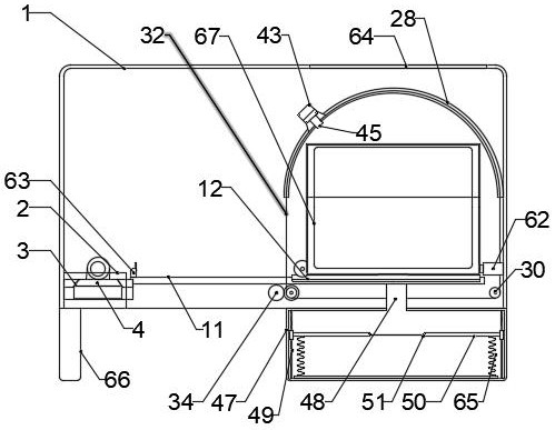
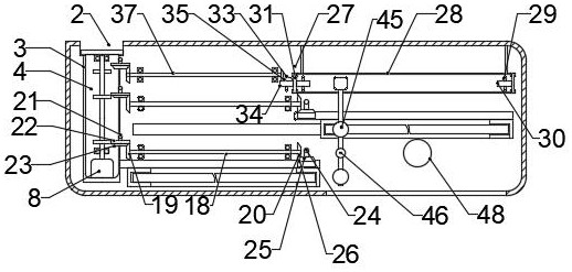
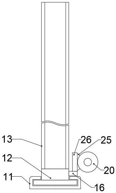
[0031] The present invention will be specifically described below with reference to the drawings. Figure 1-12 As shown, a high school physical optical test presentation device includes a rectangular casing 1, a rectangular casing 1 is provided with a diffraction experimental mechanism, and the upper surface of the rectangular case 1 is provided with a power transmission mechanism, and a medium is provided on one side of the power transmission mechanism. The replacement mechanism is provided with a light source moving mechanism on one side of the media replacement mechanism;

[0032] The power transmission mechanism includes a rectangular opening 2 of the rectangular casing 1 side surface, and the lower end of the rectangular casing 1 is opened, the trapezoidal groove 3 corresponds to the position of the rectangular opening 2, and the ladder slide is mounted on the inner surface of the trapezoidal groove 3. 4, the trapezoidal slide 4 is slidable with the trapezoidal groove 3, and t...


PUM


Abstract

A high school physics optical test demonstration device comprises a rectangular box body, a diffraction experiment mechanism is arranged below the rectangular box body, a power transmission mechanismis arranged on the upper surface of the lower end of the rectangular box body, a medium replacement mechanism is arranged on one side of the power transmission mechanism, and a light source moving mechanism is arranged on one side of the medium replacement mechanism. The beneficial effects of the invention are that the device can visually display refractive indexes of different media through the function of the medium replacement mechanism, can observe related optical parameters through adjusting the incident angle of light, can demonstrate a common light phenomenon more clearly, and enables students to learn and understand related knowledge more easily.

Description

Technical field [0001] The present invention relates to the technical field of optical experimental textbooks, and more particularly to a high school physical optical test presentation device. Background technique [0002] Optics is to study light behavior and properties, as well as physical disciplines that interact with light and substances. The origin of optics has long been described in the West. Traditional optical optics only studies visible light. Modern optical has been extended to the research of electromagnetic waves in all-band. The optical truly formed a science should be established from establishing reflex law and refractivement law. Incounting, these two laws have laid the foundation of geometric optics. [0003] Common optical phenomena has light refraction, reflection of light, diffraction of light, and interference, common optical test demonstration equipment, such as patent name 201420101687.3 Patent name is a built-in geometric optical integrated laboratory, w...

Claims


Application Information

Patent Timeline
Patent Type & Authority Applications(China)
IPC IPC(8): G09B23/22
CPCG09B23/22
Inventor 赵新广
Owner 邯郸市丛台区世天科技有限公司
Learn More