
Wood cutting device for civil engineering

A cutting device, a technology of civil engineering, applied in wood processing appliances, manufacturing tools, transportation and packaging, etc., can solve the problems of affecting cutting accuracy, reducing stability, time-consuming and laborious, etc., to ensure cutting accuracy, improve stability, prevent shaking effect

Inactive Publication Date: 2021-03-23
高旭辉
View PDF10 Cites 3 Cited by
  • Summary
  • Abstract
  • Description
  • Claims
  • Application Information

AI Technical Summary

Benefits of technology

This new technology allows for efficient use of space while also providing better control over how much material needs to be processed or removed from them. By utilizing multiple motors instead of one, these systems save more energy than traditional methods like manually scrapers. Additionally, they have features such as adjustable length and position sensitivity, allowing users to easily change their settings based upon different types of materials being worked on. Overall, this innovation helps improve efficiency and productivity across various industries.

Problems solved by technology

This patented describes an apparatus called a wooden saw machine that helps people working inside concrete constructions without having to handle them themselves. However, current methods require manual effort and slow down their progress due to issues like unevenness between different parts being worked together. Additionally, some areas may contain harmful substances causing health hazards when workers enter these locations.

Method used


Image

  • Wood cutting device for civil engineering
  • Wood cutting device for civil engineering
  • Wood cutting device for civil engineering

Examples


Embodiment Construction

[0026] In order to make the technical means, creative features, goals and effects achieved by the present invention easy to understand, the present invention will be further described below in conjunction with specific embodiments.

[0027] In the description of the present invention, it should be noted that the terms "upper", "lower", "inner", "outer", "front end", "rear end", "both ends", "one end", "another end" The orientation or positional relationship indicated by etc. is based on the orientation or positional relationship shown in the drawings, and is only for the convenience of describing the present invention and simplifying the description, rather than indicating or implying that the referred device or element must have a specific orientation, use a specific Azimuth configuration and operation, therefore, should not be construed as limiting the invention. In addition, the terms "first" and "second" are used for descriptive purposes only, and should not be understood ...


PUM


Abstract

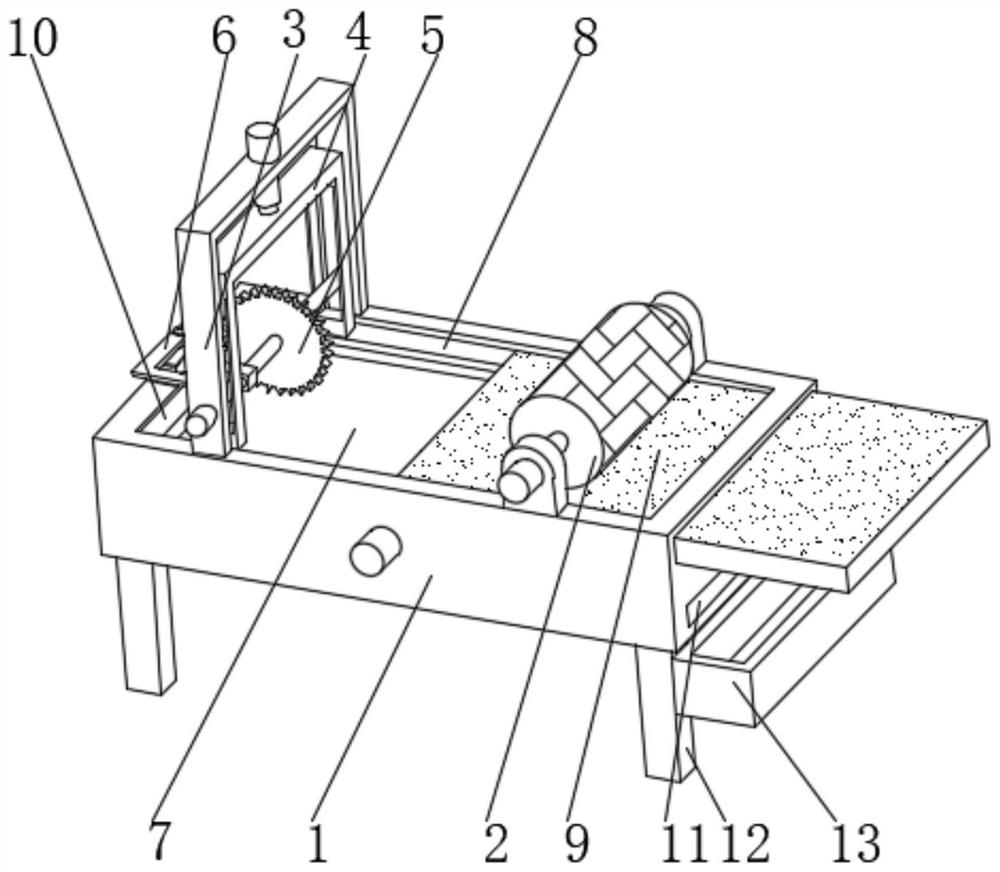
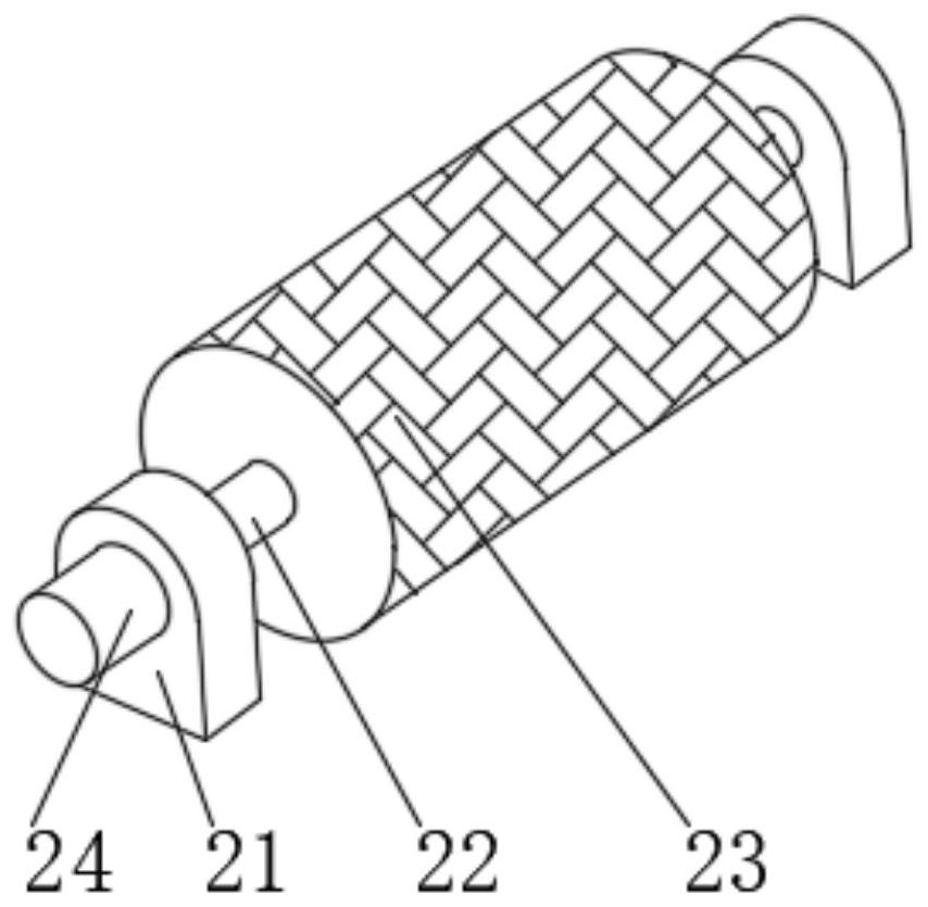
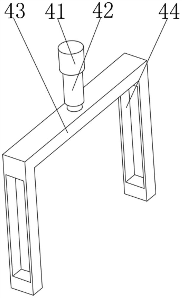
The invention discloses a wood cutting device for civil engineering. The wood cutting device for civil engineering comprises a machining table; a rolling pushing device is arranged on the right portion of the upper end of the machining table; a U-shaped frame is fixedly installed on the left portion of the upper end of the machining table; a telescopic clamping device is arranged in the middle ofthe upper end of the U-shaped frame; a cutting device body is arranged on the lower portion of an inner cavity of the U-shaped frame; a sprinkling device is arranged on the middle side of the left portion of the upper end of the machining table; a dumping device is arranged in the middle of an inner cavity of the machining table; the front side and the rear side of the upper portion of the inner cavity of the machining table are each provided with a limiting groove; the right portions of the groove walls of the two limiting grooves are jointly and movably connected with wood; and the upper portion of the left end and the upper portion of the right end of the machining table are each provided with a through groove. According to the wood cutting device for civil engineering, when an abrasiveroller rolls, wood is pushed by friction force generated between the abrasive roller and the wood to move leftwards to be fed and machined, manual carrying and pushing are not needed, and time and labor are saved.

Description


Claims


Application Information

Patent Timeline
Owner 高旭辉
Learn More