Manually-assisted agricultural conveying and picking machine with multi-angle adjustment and positioning
A technology of adjusting positioning and artificial assistance, which is applied in the direction of picking machines, agricultural machinery and tools, agriculture, etc., can solve the problems of inconvenient picking, achieve the effects of reducing water loss, solving falling, and improving picking efficiency
- Summary
- Abstract
- Description
- Claims
- Application Information
AI Technical Summary
Problems solved by technology
Method used
Image
Examples
Embodiment 1
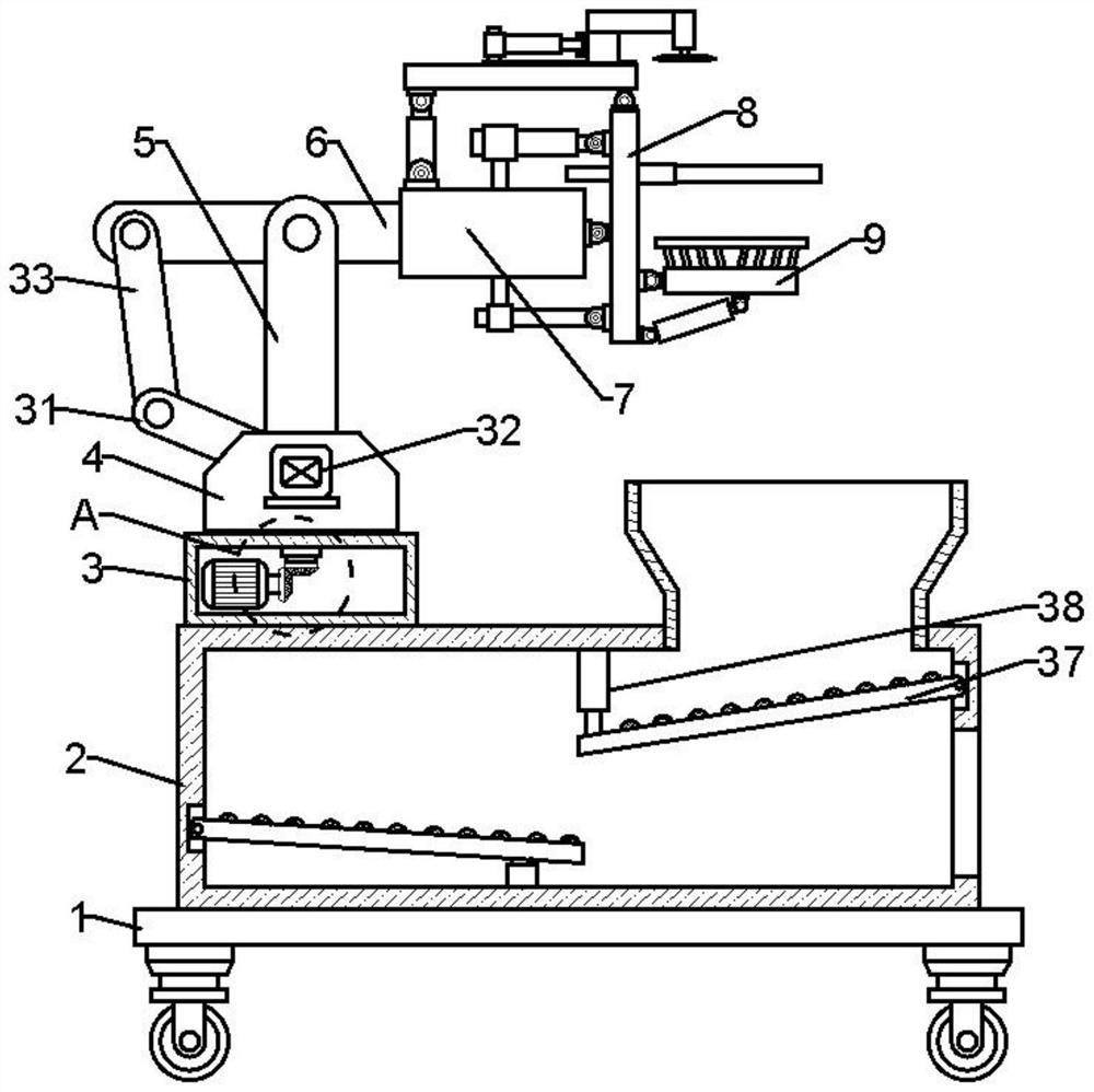
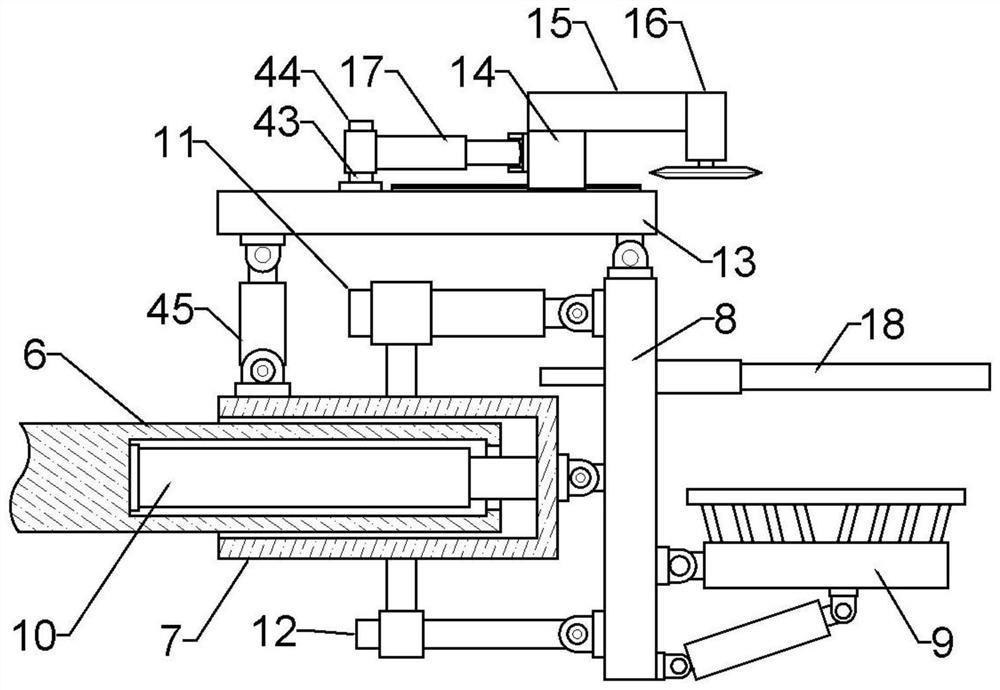
[0032] Embodiment 1: In order to achieve the purpose of durian picking, this embodiment provides an artificially assisted agricultural conveying and picking machine with multi-angle adjustment and positioning, see Figure 1-10 Specifically, it includes a bottom plate 1, a rotating assembly, an adjustment assembly, a clamping mechanism and a cutting mechanism, the bottom plate 1 is a horizontally arranged rectangular plate, and a rectangular storage box 2 is fixed on the top surface of the bottom plate 1, so A rectangular equipment box 3 is fixed on one side of the top surface of the storage box 2, and a rotating assembly is arranged in the equipment box 3; The rear end in the slot of the rotating base 4 is vertically fixed with a support column 5, and the adjustment assembly is arranged at the front end of the slot in the rotating base 4; the top end of the support column 5 is provided with a rectangular connecting groove, and the A round rod is fixed longitudinally in the gro...
Embodiment 2
[0038] Embodiment 2: In Embodiment 1, there is also the problem that the cutting angle is inconvenient to adjust again. Therefore, on the basis of Embodiment 1, this embodiment also includes: the middle of the top surface of the fixing plate 13 is laterally fixed with an arc. A motor box 14 is movably provided on the arc-shaped slide rail, and an arc-shaped chute is laterally opened in the middle of the bottom surface of the motor box 14 in cooperation with the arc-shaped slide rail; the top surface of the motor box 14 is laterally fixed There is a beam 15, and a rectangular cavity is opened in the beam 15. The outer end of the beam 15 is vertically fixed with a rectangular box 16; the top side of the fixing plate 13 is fixed to a bearing, and the inner part of the bearing A rotating stop rod 43 is vertically fixed in the ring, and a connecting sleeve 44 is fixedly sleeved on the rod body of the rotating stop rod 43, and a third electric push cylinder 17 is laterally fixed on o...
Embodiment 3
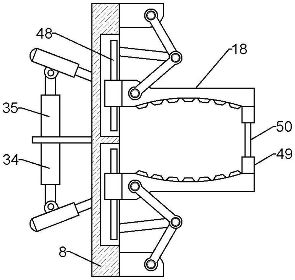
[0039] Embodiment 3: In the present invention, there is still a situation in which the size of the object cannot be adjusted and clamped. Therefore, on the basis of Embodiment 1, a clamping mechanism is also provided. The clamping mechanism includes an L-shaped pressing rod 35 and a rotating round rod 36. , double-section connecting rod 46, push rod 47, cylindrical block 49, insert rod 50, the front and rear ends of the through-holes are vertically fixed with a rotating round rod 36, and the rod body of each said rotating round rod 36 is The L-shaped pressing rod 35 is hinged horizontally; the bending end of each L-shaped pressing rod 35 is horizontally hinged with a push rod 47; The outer ends of the double-section connecting rods 46 are articulated on each of the fixed blocks, and the inner ends of the two double-section connecting rods 46 are respectively articulated with the inner ends of the two arc-shaped splints 18; The other end of the rod 47 is articulated with the mi...
PUM
 Abstract
Description
Claims
Application Information
 - R&D
- Intellectual Property
- Life Sciences
- Materials
- Tech Scout
- Unparalleled Data Quality
- Higher Quality Content
- 60% Fewer Hallucinations
Browse by: Latest US Patents, China's latest patents, Technical Efficacy Thesaurus, Application Domain, Technology Topic, Popular Technical Reports.
© 2025 PatSnap. All rights reserved.Legal|Privacy policy|Modern Slavery Act Transparency Statement|Sitemap|About US| Contact US: help@patsnap.com


