Seedling-raising grafting device for garden engineering
A technology for engineering and gardening, applied in the field of planting and grafting equipment for garden engineering, can solve the problems of inconvenient plant protection and low grafting success rate, and achieve the effects of convenient transportation and transfer, beneficial to growth and improved success rate.
- Summary
- Abstract
- Description
- Claims
- Application Information
AI Technical Summary
Problems solved by technology
Method used
Image
Examples
Embodiment 1
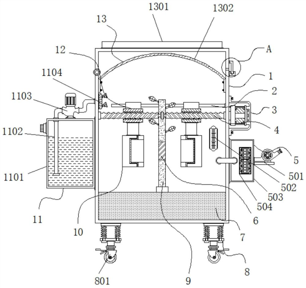
[0035] Example 1: See Figure 1-6 , a kind of seedling grafting equipment for garden engineering, comprising a box body 1 and a cultivation soil 7, the cultivation soil 7 is arranged at the bottom end inside the box body 1, the top of the box body 1 is provided with a structure 13 for daylighting and heat preservation, and one side of the box body 1 A temperature regulating mechanism 5 is arranged near the bottom end, a seedling raising body 9 is arranged at the middle position of the top of the cultivation soil 7, a grafting part 6 is arranged on the seedling raising body 9, and a spraying mechanism 11 is arranged on the other side of the box body 1. The four corners at the bottom of the box body 1 are provided with a convenient transfer structure 8, and the interior of the box body 1 is provided with a grafting site protection structure;
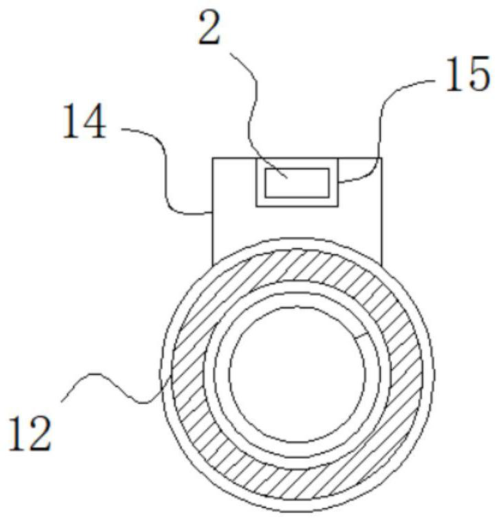
[0036] see Figure 1-6, a seedling grafting equipment for garden engineering also includes a grafting site protection structure, the gra...
Embodiment 2
[0040] Embodiment 2: The temperature regulating mechanism 5 is made up of fan 501, thermometer 502, heating box 503 and electric heating tube 504, and heating box 503 is fixedly connected at the position near the bottom end of box body 1 side, and one side of heating box 503 is fixedly connected with The fan 501, the model of the fan 501 can be FBT35-11-3.55, the inside of the heating box 503 is fixedly connected with an electric heating tube 504, and the thermometer 502 is fixedly connected to one side of the front end of the box body 1;
[0041] Specifically, such as figure 1 As shown, when in use, the thermometer 502 will monitor the temperature inside the cabinet 1 in real time. If the temperature is low, first power on the electric heating tube 504, and then start the fan 501, and the electric heating tube 504 will send the fan 501 into the cabinet 1 The inner wind heating makes the inside of the casing 1 inject hot air, so that the temperature inside the casing 1 can be ...
Embodiment 3
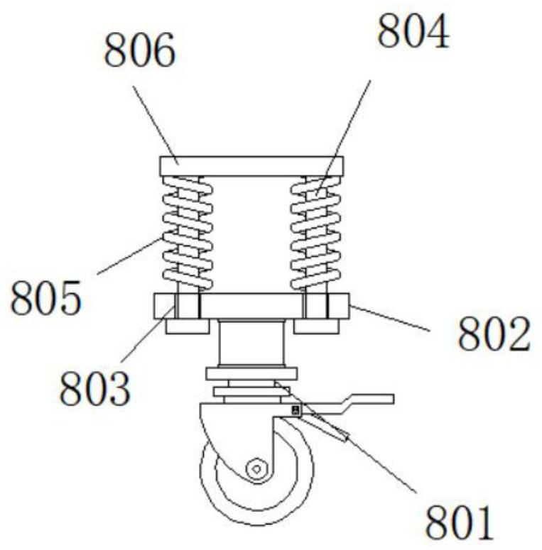
[0042] Embodiment 3: The convenient transfer structure 8 is composed of a universal wheel 801, a support plate 802, a through hole 803, a telescopic rod 804, a spring 805 and a fixed plate 806, and the fixed plate 806 is fixedly connected to the four corners at the bottom of the box body 1 respectively The two sides of the bottom end of the fixed plate 806 are respectively fixedly connected with telescopic rods 804, the outside of the telescopic rods 804 is sleeved with a spring 805, the bottom end of the spring 805 is fixedly connected with a support plate 802, and the inside of both sides of the support plate 802 is provided with through holes 803, the bottom end of the support plate 802 is fixedly connected with the universal wheel 801;
[0043] The bottom end of the telescopic rod 804 runs through the through hole 803, and the bottom end of the telescopic rod 804 is fixedly connected with a stopper, and the outer diameter of the stopper is larger than the inner diameter of ...
PUM
 Abstract
Description
Claims
Application Information
 - R&D
- Intellectual Property
- Life Sciences
- Materials
- Tech Scout
- Unparalleled Data Quality
- Higher Quality Content
- 60% Fewer Hallucinations
Browse by: Latest US Patents, China's latest patents, Technical Efficacy Thesaurus, Application Domain, Technology Topic, Popular Technical Reports.
© 2025 PatSnap. All rights reserved.Legal|Privacy policy|Modern Slavery Act Transparency Statement|Sitemap|About US| Contact US: help@patsnap.com


