
Eureka
For R&D, Eureka makes reading and utilizing patents & technical documents easy.
Eureka AIR
Designed for self-driven R&D workflows. Generate viable solutions, solve complex R&D challenges, empower your innovation with AI.

Eureka Materials
Designed for material experts only. Revolutionize your material R&D, from search, analyze, to developing new materials.

TechResearch
Generate reliable direction feasibility study reports for your R&D in just a few steps.

TechSeek
Discover and master advanced knowledge NOW. Basics, ideas, possibilities, all at once.

TechMind
As an expert in R&D Theories, TechMind can generates customized viable solutions instantly.

TechRisk
Analyze your overall solution with one click, know your potential R&D risks in advance.

TechMonitor
Get weekly tech updates, stay abreast of the latest tech innovations and key insights.
Lawn laying equipment
A kind of equipment and lawn technology, which is applied in the field of lawn laying equipment, can solve the problems of tight fit of soil, difficulty in rooting, uneven lawn strength, etc., and achieve the effect of complete scratching of equipment and reduction of adhesion
- Summary
- Abstract
- Description
- Claims
- Application Information
AI Technical Summary
Problems solved by technology
Method used
Image

Examples
Embodiment 1
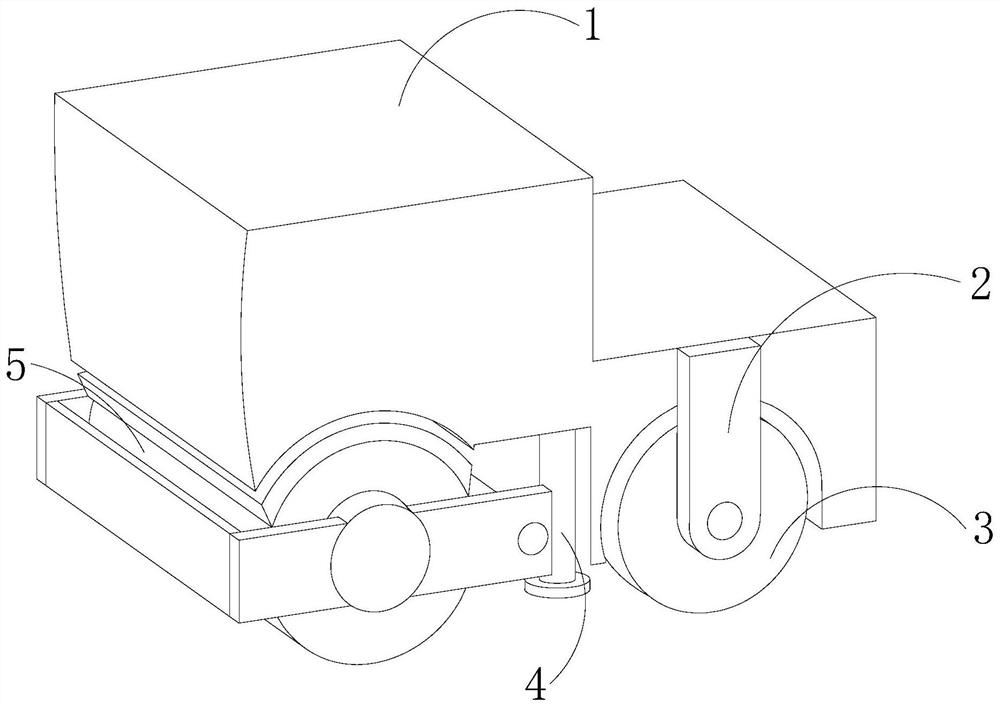
[0028] see Figure 1-Figure 5 , a lawn laying equipment, its structure includes an operator 1, a driving rod 2, a driving wheel 3, a bracket 4, and a rolling block 5, the operator 1 is embedded and connected with the driving rod 2, and the driving rod 2 moves The shaft is movably connected to the driving wheel 3, the manipulator 1 is fixedly connected to the bracket 4, and the rolling block 5 is mechanically connected to the manipulator 1;
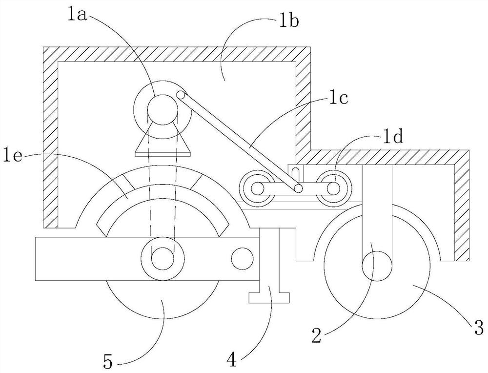
[0029] The manipulator 1 is provided with a driven wheel 1a, a box body 1b, a connecting rod 1c, a gear 1d, and a leveler 1e. The driven wheel 1a is movably engaged with the box body 1b, and the connecting rod 1c is connected to the gear 1d through a movable shaft. Flexible connection, the leveler 1e is mechanically connected with the box body 1b to remove soil clods on the rolling structure.
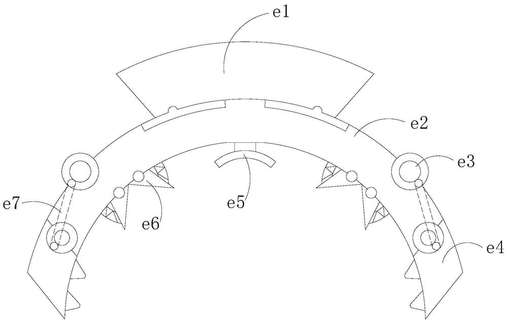
[0030] The leveler 1e is provided with a snapper e1, a fitting shaft e2, a ring shaft e3, a knocking body e4, a scratcher e5, a hook block e6, and...
Embodiment 2
[0038] see Figure 1-Figure 6 , a lawn laying equipment, its structure includes an operator 1, a driving rod 2, a driving wheel 3, a bracket 4, and a rolling block 5, the operator 1 is embedded and connected with the driving rod 2, and the driving rod 2 moves The shaft is movably connected to the driving wheel 3, the manipulator 1 is fixedly connected to the bracket 4, and the rolling block 5 is mechanically connected to the manipulator 1;
[0039] The manipulator 1 is provided with a driven wheel 1a, a box body 1b, a connecting rod 1c, a gear 1d, and a leveler 1e. The driven wheel 1a is movably engaged with the box body 1b, and the connecting rod 1c is connected to the gear 1d through a movable shaft. Flexible connection, the leveler 1e is mechanically connected with the box body 1b to remove soil clods on the rolling structure.
[0040] The leveler 1e is provided with a snapper e1, a fitting shaft e2, a ring shaft e3, a knocking body e4, a scratcher e5, a hook block e6, and...
PUM
 Abstract
Description
Claims
Application Information
 - R&D Engineer
- R&D Manager
- IP Professional
- Industry Leading Data Capabilities
- Powerful AI technology
- Patent DNA Extraction
Browse by: Latest US Patents, China's latest patents, Technical Efficacy Thesaurus, Application Domain, Technology Topic, Popular Technical Reports.
© 2024 PatSnap. All rights reserved.Legal|Privacy policy|Modern Slavery Act Transparency Statement|Sitemap|About US| Contact US: help@patsnap.com