Metal powder spray head equipment

A metal powder and equipment technology, applied in the field of metal powder molding equipment, can solve the problems of lack of precision, inability to adjust the amount of metal powder sprayed at the end, and the actual working efficiency of the equipment, etc., and achieve the effect of simple equipment structure.

Inactive Publication Date: 2021-03-26
胡月明
View PDF0 Cites 0 Cited by
  • Summary
  • Abstract
  • Description
  • Claims
  • Application Information

AI Technical Summary

Problems solved by technology

[0002] There are many shortcomings in the existing equipment. The existing metal powder nozzles often use gas mixing to drive the metal powder to be ejected from the nozzle during the molding process. At this time, due to the uncontrollable The amount of ejection will not be able to make the equipment in the actual work process, due to the long-term work may cause the lack of precision, at this time the equipment needs to be adjusted to make the equipment in a good working condition, but because the metal powder cannot be adjusted The amount of discharge at the end causes the working accuracy of the equipment to gradually decrease and the equipment cannot meet the actual needs, and if the equipment is shut down for maintenance, it will increase the labor burden of the personnel and reduce the actual working efficiency of the equipment. In some equipment, the above shortcomings cannot be overcome, which reduces the efficiency of the equipment and requires frequent maintenance and repairs

Method used


Image

  • Metal powder spray head equipment
  • Metal powder spray head equipment
  • Metal powder spray head equipment

Examples


Embodiment Construction

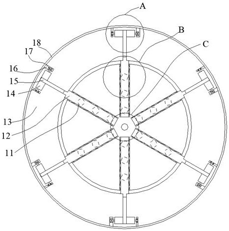
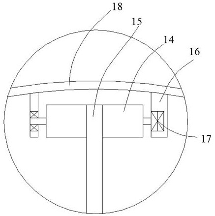
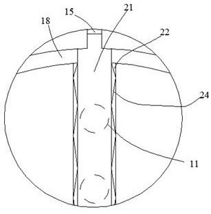
[0026] like Figure 1-Figure 7 As shown, the present invention is described in detail. For the convenience of description, the orientations mentioned below are now stipulated as follows: figure 1 The up, down, left, right, front and back directions of the projection relationship are the same. The metal powder spray head equipment of the present invention includes a matching cylinder 18, and a ring cavity 13 is arranged inside the matching cylinder 18, and a number of drop holes are connected in the matching cylinder 18. Holes 11, the drop holes 11 are arranged in an annular array, and a pumping device for pumping out metal powder is provided on one side of the drop holes 11, and a plurality of sliding stops are arranged on the ring cavity 13 and the sliding inside the cylinder body 18. The plate 12, the matching cylinder 18 and the ring cavity 13 are provided with a spout opening and closing device that drives the sliding baffle 12 to move the falling hole 11 at different posi...


PUM


Abstract

The invention discloses metal powder spray head equipment. The equipment comprises a matching cylinder, an annular cavity is formed in the matching cylinder, a plurality of falling holes are formed inthe matching cylinder in a communicating mode, the falling holes are formed in an annular array mode, and pumping-out devices used for pumping out metal powder are arranged on the sides of the falling holes. A plurality of sliding baffles are arranged in the annular cavity and the matching cylinder in a sliding mode, and nozzle opening and closing devices for driving the sliding baffles to move to enable the falling holes in different positions to be in an open or closed state are arranged in the matching cylinder and the annular cavity.

Description

technical field [0001] The invention relates to the technical field of metal powder molding equipment, in particular to metal powder nozzle equipment. Background technique [0002] There are many shortcomings in the existing equipment. The existing metal powder nozzles often use gas mixing to drive the metal powder to be ejected from the nozzle during the molding process. At this time, due to the uncontrollable The amount of ejection will not be able to make the equipment in the actual work process, due to the long-term work may cause the lack of precision, at this time the equipment needs to be adjusted to make the equipment in a good working condition, but because the metal powder cannot be adjusted The amount of discharge at the end causes the working accuracy of the equipment to gradually decrease and the equipment cannot meet the actual needs, and if the equipment is shut down for maintenance, it will increase the labor burden of the personnel and reduce the actual work...

Claims


Application Information

Patent Timeline
Patent Type & Authority Applications(China)
IPC IPC(8): B05B7/14B05B7/12B22F3/00B22F12/53
CPCB05B7/12B05B7/1436B22F3/003
Inventor 胡月明
Owner 胡月明
Why Eureka
Try Eureka