Mechanical lagging ejection device

An ejection device and lagging technology, which is applied in the field of automobile stamping dies, can solve the problems of unavailable normal production, high cost, mold cavity space range, and inability to approve and use the mold, so as to avoid the effect of ejection deformation and scrapping

Active Publication Date: 2021-03-26
东实(武汉)实业有限公司
View PDF11 Cites 0 Cited by
  • Summary
  • Abstract
  • Description
  • Claims
  • Application Information

AI Technical Summary

Problems solved by technology

However, at present, the force of most mold nitrogen springs is always in a non-linear gradual change state with the change of compression stroke, resulting in the "double-active" structure molding mold using nitrogen springs in the actual production of thin plate parts. It is easy to cause the workpiece to be pressed and deformed by the blank holder (ejector) of the lower mold (the speed of the upward movement of the binder core, the workpiece and the blank holder during the return process of the slider of the press changes from slow to fast, and the concave m

Method used


Image

  • Mechanical lagging ejection device
  • Mechanical lagging ejection device
  • Mechanical lagging ejection device

Examples


Embodiment Construction

[0030] The present invention will be further described in detail below in conjunction with the accompanying drawings, so that those skilled in the art can implement it with reference to the description.

[0031] It should be noted that, in the description of the present invention, the terms "horizontal", "vertical", "upper", "lower", "front", "rear", "left", "right", "vertical", The orientation or positional relationship indicated by "horizontal", "top", "bottom", "inner", "outer", etc. is based on the orientation or positional relationship shown in the drawings, and is only for the convenience of describing the present invention and simplifying the description, and It is not to indicate or imply that the device or element referred to must have a particular orientation, be constructed in a particular orientation, or operate in a particular orientation, and thus should not be construed as limiting the invention.

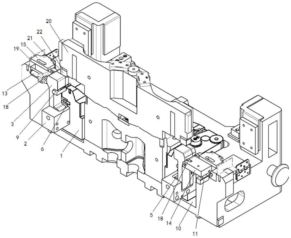
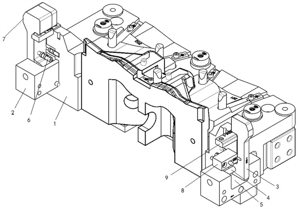
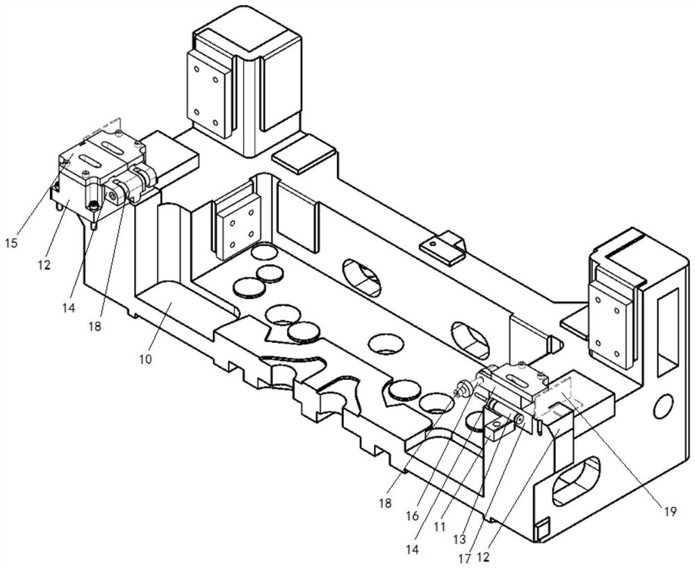
[0032] Figures 1 to 4 In order to clearly show the structure a...


PUM


Abstract

The invention discloses a mechanical lagging ejection device. A stamping workpiece is located between an upper die pressing core and a lower die blank holder to be stamped and formed and ejected out.The mechanical lagging ejection device comprises a rotary supporting assembly, a side face driving assembly, an upper strength supporting block and an adjusting cushion block. The rotary supporting assembly is installed on the side face of a lower die blank holder body and comprises a profiling supporting block installation base, a profiling rotary supporting block, a first rotary shaft, an ejection pin, an ejection pin spring, an ejection pin fixing pressing plate and a lower strength supporting block. The side face driving assembly is installed on a lower convex die base body and comprises adriving block installation base, a nitrogen spring, a sliding plate, a second rotary shaft, a roller, a driving block positioning key, a sliding plate cover plate and a protection plate. The mechanical lagging ejection device has a function of preventing the stamping workpiece from being ejected and deformed through mechanical lagging movement, effectively solves the problem that the stamping workpiece is prone to being ejected and deformed by the blank holder (ejector), and has the characteristics of being simple and convenient, low in manufacturing cost, reasonable and scientific in use andhigh in universality.

Description

technical field [0001] The invention relates to the technical field of automobile stamping dies. More specifically, the present invention relates to a mechanical hysteresis ejector. Background technique [0002] In the production process of deep press forming of sheet metal parts, usually due to product technology and appearance quality requirements, the mold is designed as a complex "double active" press forming structure, so as to better meet the mold pressing anti-wrinkle and top piece function requirements . At the same time, in order to improve the production efficiency of the parts, ensure the stable production quality and shorten the installation time of the die, the production unit will also require the pressing core of the upper die and the blank holder (ejector) of the lower die to adopt the arrangement of standard nitrogen springs to provide pressing and Push out the power. However, at present, the force of most mold nitrogen springs is always in a non-linear g...

Claims


Application Information

Patent Timeline
IPC IPC(8): B21D45/04
CPCB21D45/04
Inventor 马梨哲李康罗洪松陈毅茹承曦王韦余冬晴吴娟朱汉强陈亚鑫
Owner 东实(武汉)实业有限公司
Why Eureka
Try Eureka