

Flame-proof fibre product molding method and special equipment thereof
A technology of refractory fibers and molding methods, which is applied in ceramic molding machines, manufacturing tools, pressing rollers, etc., can solve the problems of inability to manufacture refractory products, poor fiber interweaving structure, uneven hardness, etc., so as to avoid difficulty in demoulding, The effect of uniform fiber interweaving and simple structure in the product
- Summary
- Abstract
- Description
- Claims
- Application Information
AI Technical Summary
Problems solved by technology
Method used
Image

Examples
Embodiment 1
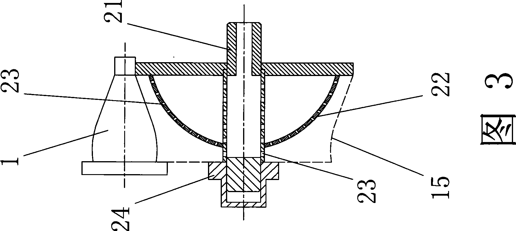
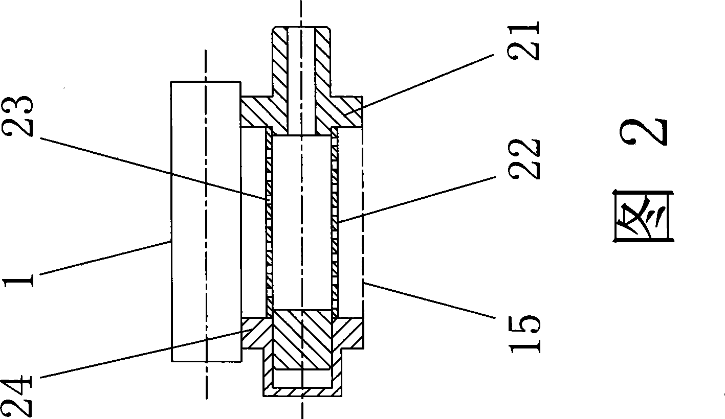
[0025] A method for forming refractory fiber products, as shown in Figures 2 and 3, comprising a mold 2 that can rotate around a fixed axis and a pressure roller 1 that cooperates with the mold 2 for rolling, and the mold 2 is provided with an adsorption surface 22, which absorbs There are several suction holes 23 connected to the negative pressure source distributed on the surface 22, according to the following steps:
[0026] 1) Watering—the mold 2 rotates forward, turns on the negative pressure source, and pours the prepared refractory fiber suspension slurry on the adsorption surface 22 of the mold 2; wherein, the refractory fiber suspension slurry The solvent water is separated by suction and filtration through a negative pressure source, and the refractory fiber mixture in the refractory fiber suspension slurry is adsorbed on the adsorption surface 22 of the mold 2;
[0027] 2) Forming——After pouring the refractory fiber suspension slurry for many times, the refractory f...
Embodiment 2
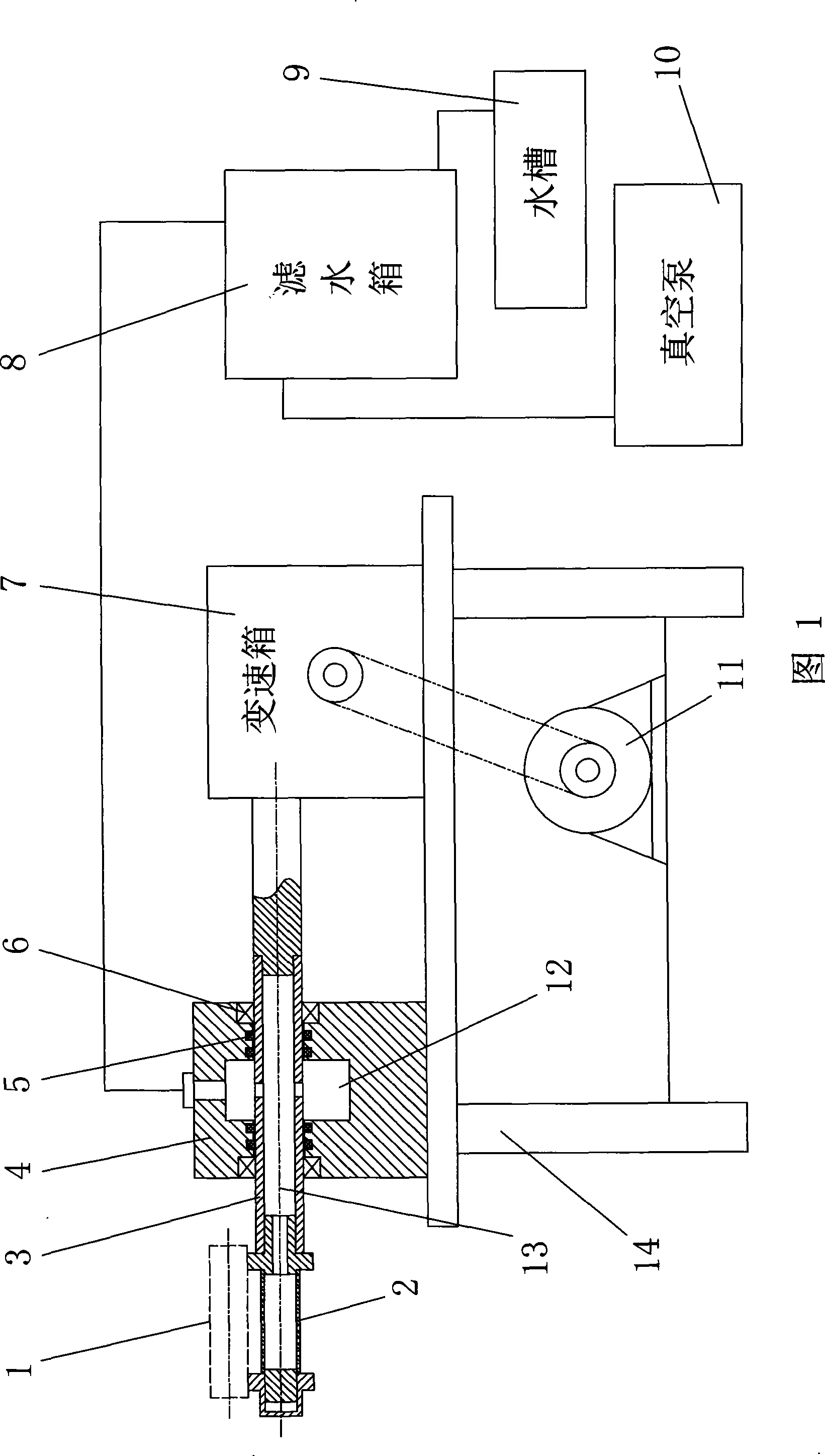
[0035] The special equipment for the above-mentioned refractory fiber product molding method as shown in Figure 1 includes a rotating shaft 3 connected to the mold 2, and the suction hole 23 on the mold 2 is connected to the filter through the suction channel 13 arranged on the rotating shaft 3. The water tank 8 is communicated, the filter water tank 8 is connected with the vacuum pump 10, and the rotating shaft 3 is connected with the motor 11 through the gearbox 7; The air suction channel 13 on the top is connected to the sealing chamber 12, the sealing chamber 12 is connected to the water filter tank 8, and the rotating shaft 3 is sealed and connected to the rotating shaft seat 4 through the sealing ring 5; The water tank 9 is placed; the motor 11 , the gearbox 7 and the shaft seat 4 are installed on the frame 14 .
[0036] In this embodiment, the vacuum pump 10 is the negative pressure source described in Embodiment 1.
PUM
 Abstract
Description
Claims
Application Information