

Slotting unit for digital printing production line and slotting method thereof
A digital printing and groove unit technology, applied in the field of corrugated cardboard production, can solve the problems of unsatisfactory users and low efficiency, and achieve the effect of reducing idling time and improving groove efficiency
- Summary
- Abstract
- Description
- Claims
- Application Information
AI Technical Summary
Problems solved by technology
Method used
Image

Examples
Embodiment Construction
[0027] Specific embodiments of the present invention will be described in detail below in conjunction with the accompanying drawings. It should be understood that the specific embodiments described here are only used to illustrate and explain the present invention, and are not intended to limit the protection scope of the present invention.
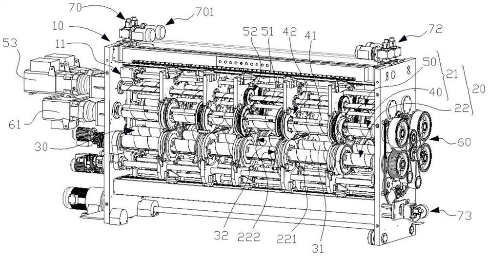
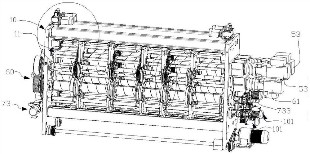
[0028] see figure 1 , figure 2 , a slotting unit for a digital printing production line, comprising a body 10, two sets of slotting devices 20 and a conveying unit 30 arranged between the two groups of slotting devices 20, the body 10 is provided with a working chamber 11, Two sets of slotting devices 20 are arranged at opposite ends of the working chamber 11, and the conveying unit 30 is arranged in the middle of the working chamber 11. The two sets of slotting devices 20 respectively slot the two ends of the indentation and scoring line of the corrugated cardboard, and convey Unit 30 conveys corrugated cardboard.
[0029] refer to ...
PUM
 Abstract
Description
Claims
Application Information