Dual-motor drive system for electric vehicle

A transmission system and electric vehicle technology, which is applied in the field of transmission system, can solve the problems of not being able to meet the driver's requirements and the gears of the reducer are few, and achieve the effect of realizing economy and power, improving power performance and reducing system cost

Inactive Publication Date: 2021-03-26
派腾奥普科技服务(北京)有限公司
View PDF0 Cites 3 Cited by
  • Summary
  • Abstract
  • Description
  • Claims
  • Application Information

AI Technical Summary

Problems solved by technology

[0002] Electric vehicles are usually equipped with a drive motor and a reducer, but because the reduc

Method used


Image

  • Dual-motor drive system for electric vehicle
  • Dual-motor drive system for electric vehicle

Examples


Embodiment Construction

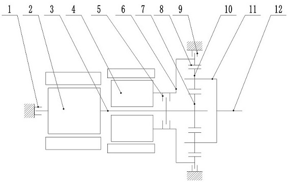
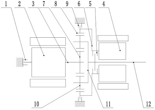
[0030] refer to figure 1 According to the first embodiment, the transmission system of the electric vehicle comprises a first lock-up clutch 1, a first motor 2, a first shaft 3, a sun gear 7, a planetary gear 10, a large ring gear 8, a planetary carrier 11, and an output shaft 12 , the second motor 4, the inter-shaft clutch 5, the second shaft 6 and the second lock-up clutch 9.

[0031] The first motor 2 has a first shaft 3 , and one end of the first shaft 3 is connected to the sun gear 7 , and the other end of the first shaft 3 is connected to the first lock-up clutch 1 . For example, the first motor 2 may be coaxially connected with the first shaft 3, and both ends of the first shaft 3 are respectively connected to the first sun gear 7 and the first lock-up clutch.

[0032] One end of the first lock-up clutch 1 is connected to the housing, and the other end of the first lock-up clutch 1 is connected to the first shaft 3. The first lock-up clutch 1 can be opened according to...


PUM


Abstract

The invention relates to a dual-motor drive system of an electric vehicle. The dual-motor drive system is provided with a first motor, a second motor and a planetary mechanism, and stepless speed change is achieved. According to the electric vehicle, by arranging the double motors and a continuously variable transmission, the working condition range of the electric vehicle is expanded, and the economical efficiency is improved.

Description

technical field [0001] The invention belongs to the field of vehicles, in particular to a transmission system for electric vehicles. Background technique [0002] Electric vehicles are usually equipped with a drive motor and a reducer, but because the reducer has fewer gears, it usually cannot meet the driver's requirements under various working conditions. Contents of the invention [0003] The object of the present invention is to propose a dual motor drive system for an electric vehicle. [0004] Specifically, it is achieved through the following technical means: [0005] A dual-motor drivetrain for an electric vehicle includes a first lock-up clutch, a first motor, a first shaft, a second motor, an inter-shaft clutch, a second shaft, a second lock-up clutch and an output shaft and a planetary gear assembly, the planetary The gear assembly includes planetary gear, planetary carrier, sun gear and large ring gear. [0006] The first motor is drivingly connected to the ...

Claims


Application Information

Patent Timeline
IPC IPC(8): B60K1/02B60K17/04
CPCB60K1/02B60K17/046
Inventor 崔小雷
Owner 派腾奥普科技服务(北京)有限公司
Why Eureka
Try Eureka