
Cleaning apparatus for cleaning a surface of a sensor apparatus

A technology of sensor equipment and cleaning equipment, which is applied in the field of sensor systems, can solve the problems of expensive system components, large cleaning agent supply, and low system efficiency, and achieve the effect of flexible structure and installation

Pending Publication Date: 2021-03-26
CONTINENTAL AUTOMOTIVE TECH GMBH
View PDF1 Cites 0 Cited by
  • Summary
  • Abstract
  • Description
  • Claims
  • Application Information

AI Technical Summary

Problems solved by technology

This makes the system less efficient, requiring larger detergent feeds and larger and thus more expensive system components

Method used


Image

  • Cleaning apparatus for cleaning a surface of a sensor apparatus
  • Cleaning apparatus for cleaning a surface of a sensor apparatus
  • Cleaning apparatus for cleaning a surface of a sensor apparatus

Examples


Embodiment approach

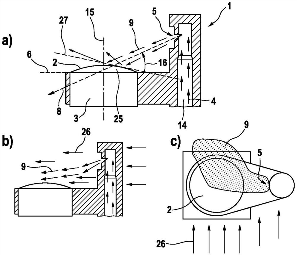
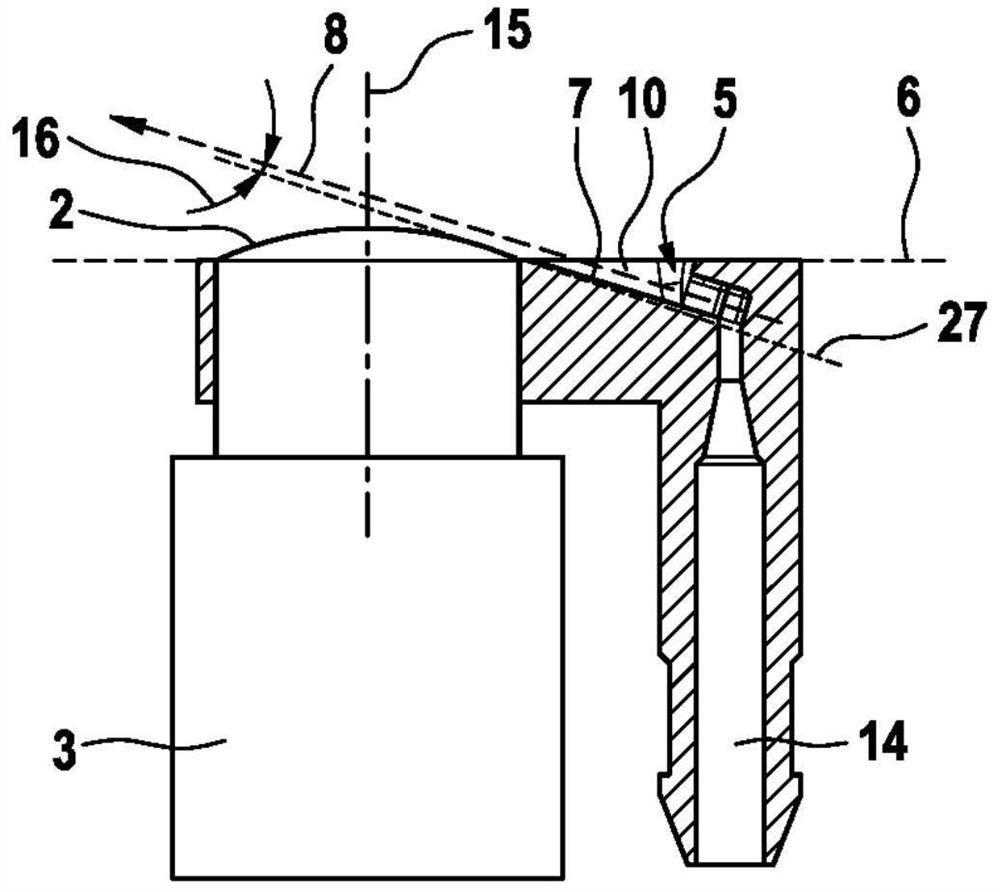
[0037] Figure 2a and Figure 2b show with figure 1 A first embodiment according to the invention of a cleaning device 1 of a similar exemplary embodiment comprises a digital camera as sensor device 3 .

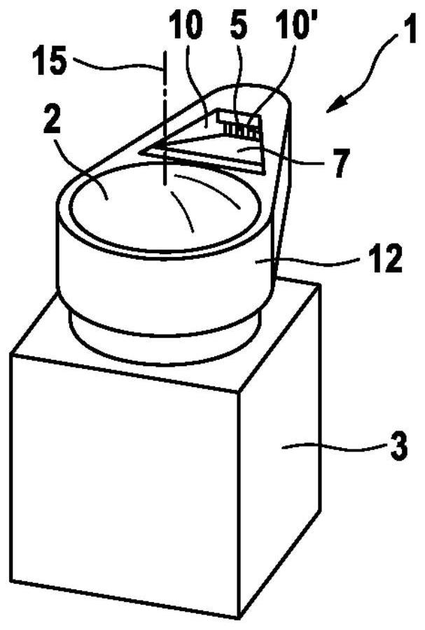
[0038] In order to achieve simplified handling and mountability, the cleaning device 1 and the sensor device 3 are combined together in a common housing 12 to form a common structural unit. The outwardly facing front surface of the housing 12 is formed flush with the surface of the outer surface area 6 and forms part of this.

[0039] The arcuate structure of the surface 2 of the camera lens is slightly convex on the surrounding outer surface region 6 . The outer surface area can actually be, for example, the outer surface of a vehicle body or a vehicle component in which the structural unit is installed.

[0040] The nozzle 5 is stationary and is positioned laterally offset relative to the sensor axis 15 , sunken below the outer surface area 6 . In the exemplary embodim...


PUM


Abstract

The invention relates to an optically and aerodynamically optimized and particularly wind-insensitive cleaning apparatus (1) for cleaning a surface of a sensor apparatus (3) of a vehicle with a fluidcleaning agent (4). The surface (2) is surrounded by an outer surface region (6) with respect to which the surface (2) is arranged so as to be substantially flush therewith or curved in a domed mannerabove it, and, in relation to the outer surface region (6), the nozzle (5) is positioned in a recessed manner such that the spraying of the cleaning agent is realized below the outer surface region (6).

Description

technical field [0001] The invention relates to a cleaning device for cleaning the surface of a sensor device, in particular a camera lens or an outer cover of an optical radar, a structural unit comprising the cleaning device and a sensor device and a device for detecting the surroundings of a vehicle A sensor system comprising at least one of the aforementioned components. Background technique [0002] Assistance systems with sensors are increasingly being installed in motor vehicles today, which assist the vehicle user while the vehicle is in motion and are intended to reliably detect and monitor the vehicle's surroundings at all times. Such auxiliary systems include optical or optoelectronic devices, such as cameras, laser-based sensors or infrared sensors, for this purpose. These devices have transparent elements, such as lenses or covers, which, depending on the application, transmit light without restriction or in a defined restricted wave range. Such transparent el...

Claims


Application Information

Patent Timeline
Patent Type & Authority Applications(China)
IPC IPC(8): B60S1/56B60S1/52
CPCB60S1/56B60S1/52B60S1/54G01S17/931G01S7/497G01S2007/4977G01S7/4813
Inventor T·哈恩D·林格勒
Owner CONTINENTAL AUTOMOTIVE TECH GMBH
Learn More