
Collet counterweight device of elevator and counterweight mounting structure applying same

An elevator and counterweight technology, which is used in elevators in buildings, transportation and packaging, and lifting equipment in mines, etc., can solve the problems of installation and operation obstacles, traction wire ropes out of groove, and high cost, and achieve convenient installation and safety. The effect of disassembly, prevention of slotting, and cost reduction

Pending Publication Date: 2021-03-26
GUANGDONG WINONE ELEVATOR
View PDF0 Cites 0 Cited by
  • Summary
  • Abstract
  • Description
  • Claims
  • Application Information

AI Technical Summary

Problems solved by technology

The traditional elevator counterweight frame consists of two left and right columns and upper and lower beams. The counterweight anti-rope pulley is installed on the upper beam of the counterweight frame. The upper beam needs to have load-bearing and specification requirements, and the cost is relatively high; when installing the counterweight When the counterweight and anti-rope pulleys hinder the installation operation, it is difficult to install the counterweight; when the height of the top layer of the hoistway is small, in order to meet the operation stroke requirements of the counterweight device, the counterweight structure can only reduce the distance between the two columns. length, and reduce the number of counterweights, but this will cause the total weight of the counterweight device to fail to meet the balance requirements of the elevator
In addition, in order to save the space of the hoistway in the traditional elevator, the guide wheel and the counterweight anti-sheave are usually arranged vertically in the hoistway plane design, and the traction wire rope needs to be installed with twists. In order to solve the above situation, it is necessary to improve the structure of the existing counterweight device

Method used


Image

  • Collet counterweight device of elevator and counterweight mounting structure applying same
  • Collet counterweight device of elevator and counterweight mounting structure applying same
  • Collet counterweight device of elevator and counterweight mounting structure applying same

Examples


Embodiment Construction

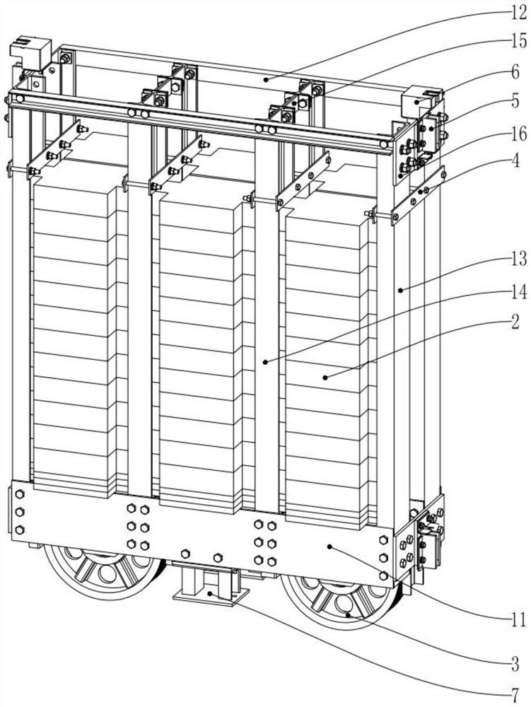
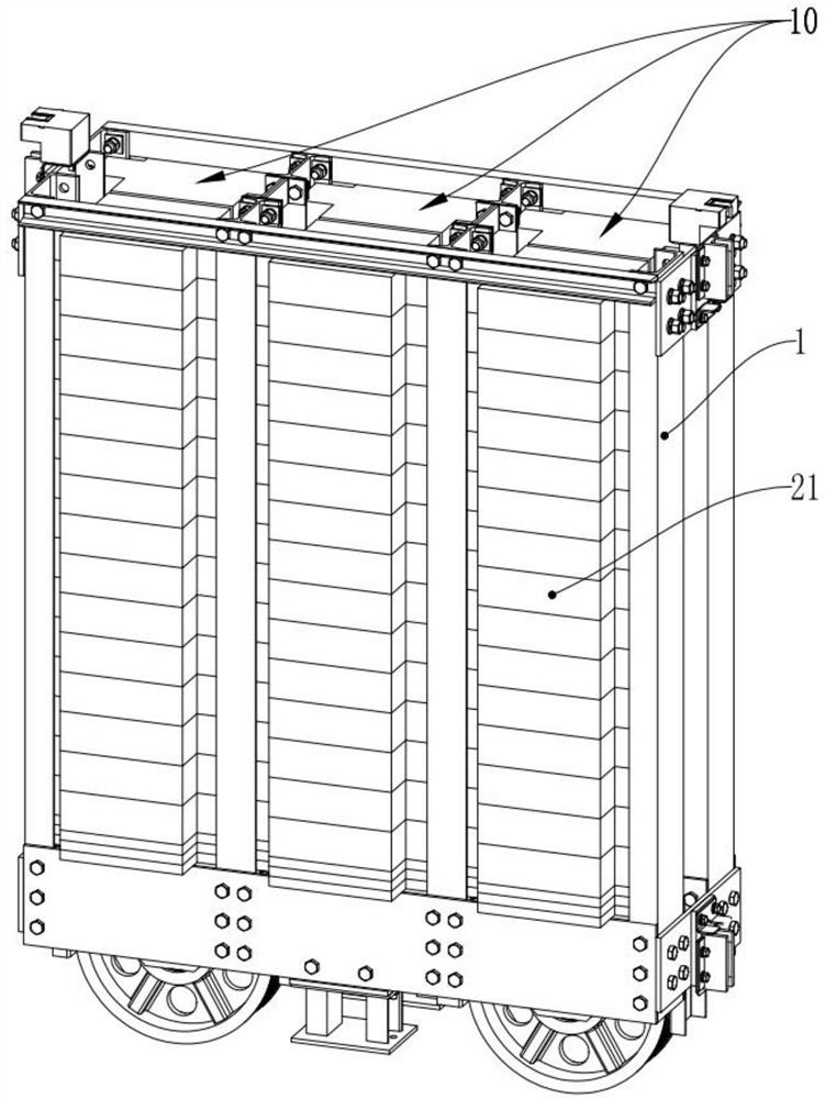
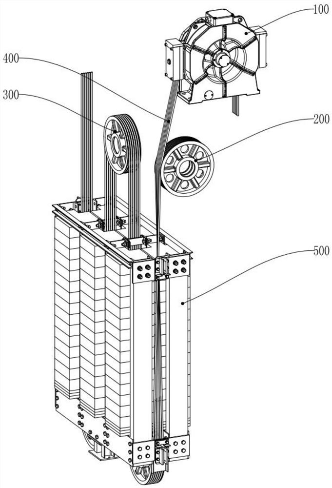
[0024] Embodiments of the present invention are described in detail below, examples of which are shown in the drawings, wherein the same or similar reference numerals designate the same or similar elements or elements having the same or similar functions throughout. The embodiments described below by referring to the figures are exemplary only for explaining the present invention and should not be construed as limiting the present invention.

[0025] In describing the present invention, it should be understood that the terms "longitudinal", "transverse", "upper", "lower", "front", "rear", "left", "right", "vertical", " The orientations or positional relationships indicated by "horizontal", "top", "bottom", "inner", "outer", etc. are based on the orientations or positional relationships shown in the drawings, and are only for the convenience of describing the present invention and simplifying the description, rather than Nothing indicating or implying that a referenced device o...


PUM


Abstract

The invention provides a collet counterweight device of an elevator and a counterweight mounting structure applying the same. The collet counterweight device comprises a counterweight rack, a counterweight group, a counterweight diversion sheave, a counterweight weight, a counterweight guide shoe and an oil cup. A bearing beam is arranged below the counterweight rack, and a plurality of counterweight cavities are formed above the bearing beam; the counterweight group is arranged in each counterweight cavity; the counterweight weight is detachably and slidably arranged on the counterweight rackfor compressing the counterweight group; and the counterweight diversion sheave is arranged below the counterweight rack. The demand on the beam on the counterweight rack is reduced, the cost is lowered, the counterweight mounting space in the counterweight rack can be utilized effectively and fully, and meanwhile, it is convenient to mount and detach the counterweight group. A condition that a traction steel wire rope and a steel wire wheel are separated in the counterweight mounting structure can be prevented effectively.

Description

technical field [0001] The invention relates to the technical field of elevator counterweight devices, in particular to a bottom bracket type counterweight device of an elevator and a counterweight installation structure using the same. Background technique [0002] The counterweight is an integral part of the elevator traction system. Its function is to balance the weight of the car itself and part of the elevator load weight, while reducing the power of the traction motor and the torque on the traction wheel or worm wheel. The counterweight device is located in the hoistway, and the car is connected by the traction wire rope through the guide wheel and the traction wheel. During the operation of the elevator, the counterweight device slides on the counterweight guide rail through the counterweight guide shoe to play a balancing role. The traditional elevator counterweight frame consists of two left and right columns and upper and lower beams. The counterweight anti-rope pu...

Claims


Application Information

Patent Timeline
IPC IPC(8): B66B17/12B66B11/08B66B11/00
CPCB66B11/0055B66B11/008B66B17/12
Inventor 陈铭其李显斌
Owner GUANGDONG WINONE ELEVATOR
Features
  • Generate Ideas
  • Intellectual Property
  • Life Sciences
  • Materials
  • Tech Scout
  • Unparalleled Data Quality
  • Higher Quality Content
  • 60% Fewer Hallucinations
Learn More