
High-rise building shear wall cylinder outwards-extending wall cap building structure system

A technology for high-rise buildings and building structures, applied in building components, special structures, building structures, etc., and can solve problems such as stress concentration

Inactive Publication Date: 2021-03-26
青岛亿联建设集团股份有限公司
View PDF4 Cites 0 Cited by
  • Summary
  • Abstract
  • Description
  • Claims
  • Application Information

AI Technical Summary

Problems solved by technology

When pouring the wall cap, it is necessary to drill holes on the pile foundation column or the shear wall cylinder to fix the pouring formwork, which will affect the local strength of the pile foundation column and the shear wall cylinder, and it is necessary to be able to improve the shear force The stress of the wall cylinder eliminates the excessive concentration of stress caused by the direct connection of the frame beam and the secondary beam with the shear wall cylinder in the prior art

Method used


Image

  • High-rise building shear wall cylinder outwards-extending wall cap building structure system
  • High-rise building shear wall cylinder outwards-extending wall cap building structure system
  • High-rise building shear wall cylinder outwards-extending wall cap building structure system

Examples


Embodiment 1

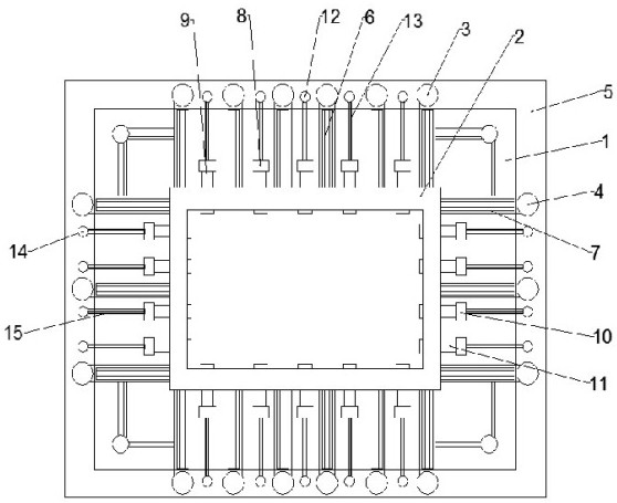
[0026] Such as Figure 1-4 As shown, the high-rise building shear wall cylinder outer extension wall cap building structure system according to the embodiment of the present invention includes a foundation pile platform 1, a shear wall cylinder 2, a fixed frame column one 3 and a fixed frame column two 4, the The shear wall cylinder body 2 and the fixed frame column one 3 and the fixed frame column two 4 are all located on the upper end of the foundation pile platform 1, and the foundation pile platform 1 is located outside the shear wall cylinder body 2 The circle is provided with a frame-shaped frame beam 5, and the two ends of the frame-shaped frame beam 5 are provided with the fixed frame column-3, and the fixed frame column-3 and the shear wall cylinder body 2 are evenly spaced. A connecting frame beam 1 6 is provided, the fixed frame column 2 4 is arranged on both sides of the frame-shaped frame beam 5, and the fixed frame column 2 4 and the shear wall cylinder 2 are pro...

Embodiment 2

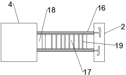
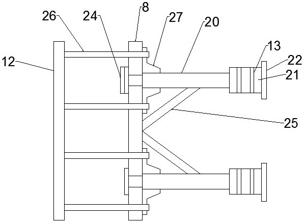
[0029] Such as Figure 1-4 As shown, the pile platform 1, the shear wall cylinder 2, the fixed frame column 1 3 and the fixed frame column 2 4 are all poured with steel bars and concrete to form a concrete steel bar structure. The first fixed frame column 3 , the second fixed frame column 4 , the first support frame column 12 and the second support frame column 14 and the foundation piles are all vertical concrete reinforcement columns. The first connecting frame beam 6, the second connecting frame beam 7, the first receiving frame beam 9, the second receiving frame beam 11, the first connecting secondary beam 13 and the second connecting secondary beam 15 are all horizontal Erected bearing beams.

[0030] Such as Figure 1-4 As shown, the connecting frame beam 1 6 and the connecting frame beam 2 7 include frame beam gluten between the fixed frame column 1 3, the fixed frame column 2 4 and the shear wall cylinder 2 16. The middle part of the frame beam gluten 16 is provided...


PUM


Abstract

The invention discloses a high-rise building shear wall cylinder outwards-extending wall cap building structure system which comprises a foundation pile platform, a shear wall cylinder, first fixing frame columns, and second fixing frame columns; the shear wall cylinder, the first fixing frame columns and the second fixing frame columns are all located at the upper end of the foundation pile platform; a frame type frame beam is arranged at the position, located on the outer circle of the shear wall cylinder, of the foundation pile platform; the first fixing frame columns are arranged at the two ends of the frame type frame beam; second bearing frame beams are fixedly connected between second foundation pile columns and the shear wall cylinder; a plurality of first supporting frame columnsare arranged at the two ends of the frame type frame beam and located between the first fixing frame columns; the first supporting frame columns are connected with first foundation pile columns through first connecting secondary beams; a plurality of second supporting frame columns are arranged at the two sides of the frame type frame beam and located between the second fixing frame columns; and the second supporting frame columns are connected with the second foundation pile columns through second connecting secondary beams. The high-rise building shear wall cylinder outwards-extending wall cap building structure system has the beneficial effects that the overall weight of a wall cap is shared by the pile foundation columns and the shear wall cylinder, so that the structural safety is guaranteed, and the practicability is improved.

Description

technical field [0001] The invention relates to the technical field of building walls, in particular to a high-rise building shear wall cylinder external extension wall cap building structure system. Background technique [0002] The shear wall cylinder structure is a space-enclosed cylinder formed by concentrating the shear walls into the interior of the house. The surrounding shear walls form a vertical thin-walled tube and pile foundation columns form a vertical box-shaped frame tube, forming a whole, and the overall wind load resistance. This kind of building structure is mostly used in service or office places such as hotels and shopping malls. In order to make the building eye-catching, building developers like to pour a wall cap above the main entrance to design the shape for publicity. Most of the existing shear wall cylinders and pile foundation columns are integrally formed by direct pouring of beams. When pouring the wall cap, it is necessary to drill holes on t...

Claims


Application Information

Patent Timeline
Patent Type & Authority Applications(China)
IPC IPC(8): E04B2/56E04B1/34E04B1/19E02D27/12
CPCE02D27/12E04B1/19E04B1/34E04B2/56
Inventor 卢志东王光张奎波黄子瑜
Owner 青岛亿联建设集团股份有限公司
Learn More