
Heat pump system and control method and device thereof, air conditioning equipment and storage medium

A heat pump system and heat mode technology are applied in the fields of control devices, air conditioning equipment, storage media, heat pump systems and control methods thereof, and can solve the problem of reducing the heat exchange capacity of heat exchangers in the heat pump system, the fluctuation of indoor temperature, and the reduction of heating capacity. and other problems to achieve the effect of improving heat exchange performance, reducing the use of electric heating devices, and improving energy efficiency

Pending Publication Date: 2021-03-26
GREE ELECTRIC APPLIANCES INC
View PDF0 Cites 3 Cited by
  • Summary
  • Abstract
  • Description
  • Claims
  • Application Information

AI Technical Summary

Problems solved by technology

Most constant temperature and humidity machines need to be equipped with electric heating devices. For example, when the indoor humidity is greater than the set humidity and the indoor temperature is less than or equal to the set temperature, in order to avoid the indoor temperature being too low, it is necessary to use an electric heating device to increase the indoor temperature; For another example, when the indoor temperature is lower than the set temperature, the indoor temperature needs to be raised, but at this time, if the outdoor heat exchanger is frosted, a part of the high-temperature and high-pressure refrigerant in the heat pump system needs to be used for defrosting, which will reduce the efficiency of the heat pump. The heat exchange capacity of the heat exchanger in the system will reduce the heating capacity and cause fluctuations in the indoor temperature. At this time, it is also necessary to use an electric heating device to adjust the indoor temperature
[0003] Although the use of electric heating devices can meet the adjustment needs of indoor temperature, it will increase power consumption and reduce energy efficiency

Method used


Image

  • Heat pump system and control method and device thereof, air conditioning equipment and storage medium
  • Heat pump system and control method and device thereof, air conditioning equipment and storage medium
  • Heat pump system and control method and device thereof, air conditioning equipment and storage medium

Examples


Embodiment Construction

[0068] The technical solutions in the embodiments of the present invention will be clearly and completely described below in conjunction with the drawings in the embodiments of the present invention. Apparently, the described embodiments are only some of the embodiments of the present invention, not all of them. Based on the embodiments of the present invention, all other embodiments obtained by persons of ordinary skill in the art without making creative efforts fall within the protection scope of the present invention.

[0069] In describing the present invention, it should be understood that the terms "center", "transverse", "longitudinal", "front", "rear", "left", "right", "upper", "lower", " The orientations or positional relationships indicated by "vertical", "horizontal", "top", "bottom", "inner" and "outer" are based on the orientations or positional relationships shown in the drawings, and are only for the convenience of describing the present invention and Simplifie...


PUM


Abstract

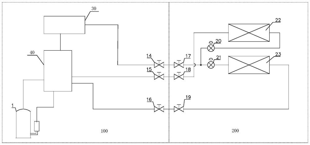
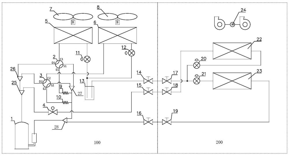
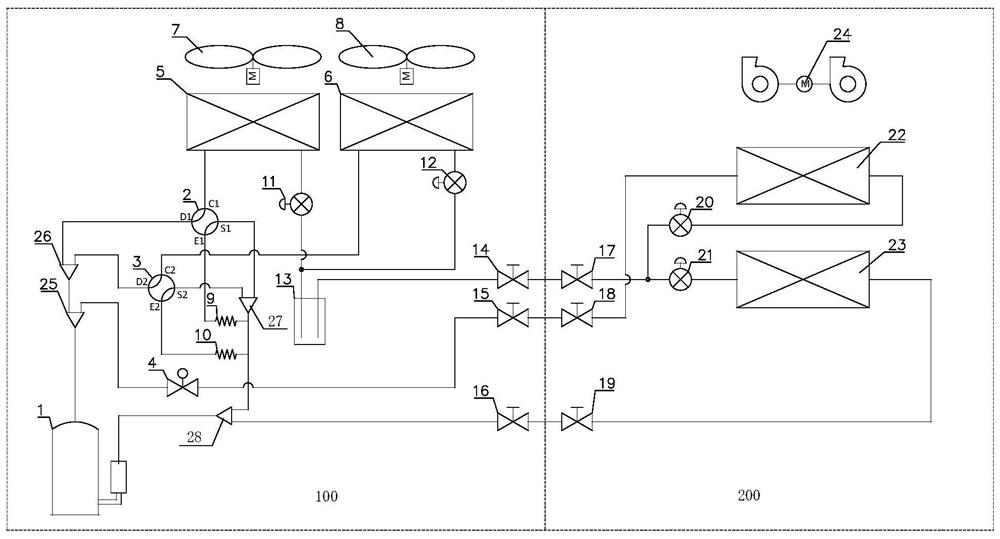
The invention relates to a heat pump system and a control method and device thereof, air conditioning equipment and a storage medium. The heat pump system comprises a compressor (1), a first indoor heat exchanger (22), a second indoor heat exchanger (23), an outdoor heat exchanger (30) and a valve assembly (40), wherein the valve assembly (40) is connected with an exhaust port and an air suction port of the compressor (1), the first indoor heat exchanger (22), the second indoor heat exchanger (23) and the outdoor heat exchanger (30), and the valve assembly (40) is configured to control the flow direction of a refrigerant and / or on-off of a connecting pipeline so as to achieve the switching between different working modes of the heat pump system; wherein the working modes comprise a refrigerating mode, a heating mode and a dehumidifying and reheating mode, and in the dehumidifying and reheating mode, the valve assembly (40) is configured to communicate the exhaust port of the compressor(1) with a first interface of the first indoor heat exchanger (22), so that the first indoor heat exchanger (22) serves as a condenser.

Description

technical field [0001] The invention relates to the technical field of air-conditioning equipment, and in particular to a heat pump system, a control method thereof, a control device, an air-conditioning equipment, and a storage medium. Background technique [0002] At present, in order to improve the comfort of the environment where people live, a constant temperature and humidity machine is used to control the temperature and humidity in the environment. Most constant temperature and humidity machines need to be equipped with electric heating devices. For example, when the indoor humidity is greater than the set humidity and the indoor temperature is less than or equal to the set temperature, in order to avoid the indoor temperature being too low, it is necessary to use an electric heating device to increase the indoor temperature; For another example, when the indoor temperature is lower than the set temperature, the indoor temperature needs to be raised, but at this time...

Claims


Application Information

Patent Timeline
Patent Type & Authority Applications(China)
IPC IPC(8): F25B13/00F25B41/20F25B41/30F25B41/31F25B47/02F25B49/02
CPCF25B13/00F25B47/02F25B49/02
Inventor 尤文超杨智峰戴永福
Owner GREE ELECTRIC APPLIANCES INC
Learn More