Underground engineering three-way loading test device and loading test method

A loading test device and underground engineering technology, applied in measuring devices, using stable tension/pressure testing material strength, instruments, etc., can solve the problem of inconvenient loading and unloading test filling materials, and achieve convenient and quick addition and cleaning, avoid Roller overload, reduced traction effect

Pending Publication Date: 2021-03-26
HUNAN INSTITUTE OF ENGINEERING
View PDF1 Cites 0 Cited by
  • Summary
  • Abstract
  • Description
  • Claims
  • Application Information

AI Technical Summary

Problems solved by technology

[0005] The purpose of the present invention is to overcome the deficiencies of the prior art, disclose a three-way loading test device and loading test method for underground engineering, solve the problem of inconvenient loading and unloading test filling materials, and realize the three-way loading test very conveniently

Method used


Image

  • Underground engineering three-way loading test device and loading test method
  • Underground engineering three-way loading test device and loading test method
  • Underground engineering three-way loading test device and loading test method

Examples


Embodiment 1

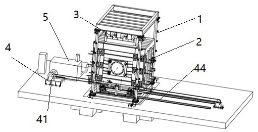
[0039] Preferred embodiment 1 of the present invention provides a kind of underground engineering three-way loading test device, with reference to Figure 1 to Figure 7 , which includes a fixed frame 1, a mobile material truck 2, a loading device 3, a traction system 4, and a hydraulic system 5, and a vertical loading device 3 is provided on the upper part of the fixed frame 1 to realize loading in the first direction from top to bottom, There is a loading device 3 on the left side of the mobile material car to realize loading in the second direction from left to right, and a loading device 3 is provided on the right side of the mobile material car to realize loading in the third direction from right to left , the second loading direction is exactly opposite to the third loading direction, perpendicular to the first vertical loading direction and on the same projected plane, the lower part of the mobile material cart 2 is provided with a traction system to realize the moving of...

Embodiment 2

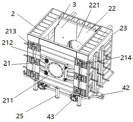
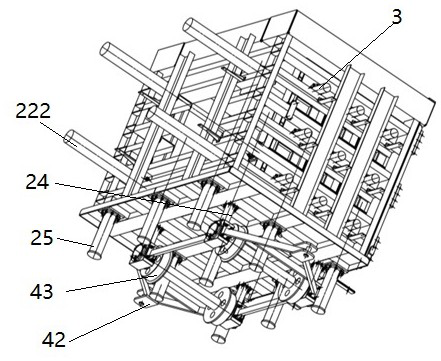
[0050] On the basis of preferred embodiment 1, such as Figure 4 As shown, further, the rear door 22 includes a rear door panel 221, a small door 211, a rear door drive cylinder 222, a rear door guide wheel 223, and a rear door guide rail 224; the rear door panel 221 is connected with the piston rod of the rear door drive cylinder 222, and the cylinder of the rear door drive cylinder 222 The seat is connected to the material trolley frame 23, the guide wheel 223 is arranged on the bottom of the rear door panel 221, the rear door panel 221 is supported on the rear door guide rail 224, the rear door guide rail 224 is installed above the bottom of the mobile material truck 2, and the rear door driving cylinder 222 drives the rear door panel 221 Realize the movement relative to the forward and backward direction of the material truck frame 23, and realize the sub-area loading test; Figure 6 Shown is a schematic diagram of the rear door 22 translation of one-third position of a ki...


PUM


Abstract

The invention discloses an underground engineering three-way loading test device which comprises a fixed frame, a movable skip car, loading devices, a traction system and a hydraulic system. The vertical loading device is arranged on the upper portion of the fixed frame, and loading in the first direction from top to bottom is achieved; the loading device is arranged on the left side of the movable skip car, so that loading in the second direction from the left to the right is realized; the loading device is arranged on the right side of the movable skip car, so that loading in the third direction from the right side to the left side is achieved, wherein the second loading direction is right opposite to the third loading direction and is perpendicular to the first vertical loading direction; and the traction system is arranged on the lower portion of the movable skip car, so that the movable skip car can be moved into or out of the fixed frame; and the hydraulic system provides pressure load for the loading devices. The invention further discloses a loading test method of the test device. By adopting the device and the method, the stress of the test model can be more practical, thetest process is more convenient and faster, and the test cost is lower.

Description

technical field [0001] The invention relates to the field of geotechnical engineering model tests, in particular to a three-way loading test device and a loading test method for underground engineering. Background technique [0002] With the continuous advancement of underground engineering represented by tunnels in our country, how to evaluate the design quality of underground tunnel engineering and how to ensure the rationality of engineering structure design is an increasingly challenging problem; its research involves geotechnical engineering , structural engineering, seepage and vibration and other mechanical fields, the impact of traffic load on engineering is also very significant. [0003] At present, there is a lack of practical and effective analysis methods at home and abroad, mainly relying on engineering experience for estimation, which has great blindness; in order to make up for the limitations of theoretical analysis and verify the rationality of theoretical ...

Claims


Application Information

Patent Timeline
IPC IPC(8): G01N3/12G01N3/02
CPCG01N3/02G01N3/12G01N2203/0019G01N2203/0048G01N2203/0256
Inventor 陈乐尧王秀珍彭浩舸黄中华其他发明人请求不公开姓名
Owner HUNAN INSTITUTE OF ENGINEERING
Why Eureka
Try Eureka