Communication wireless transmission device for mining protector

A wireless transmission and transmission device technology, which is applied in the direction of antenna support/installation device, deicing/drying device, antenna, etc., can solve the problems of inconvenient movement, unstable signal reception, troubles, etc., and achieve convenient and stable placement or movement , Improve the signal receiving strength and facilitate the effect of information transmission

Active Publication Date: 2021-03-26
HEFEI SWITCH FACTORY
View PDF11 Cites 2 Cited by
  • Summary
  • Abstract
  • Description
  • Claims
  • Application Information

AI Technical Summary

Problems solved by technology

[0003] At present, various types of wireless transmission devices are required for information transmission in the mine. Most of the wireless transmission devices need to change their positions constantly to determine the best signal position when they are in use. However, due to the large size of the general mine protector communication wireless transmission device, it is not convenient to move, and the signal reception is also unstable. Use brings greater trouble

Method used


Image

  • Communication wireless transmission device for mining protector
  • Communication wireless transmission device for mining protector
  • Communication wireless transmission device for mining protector

Examples


Embodiment 1

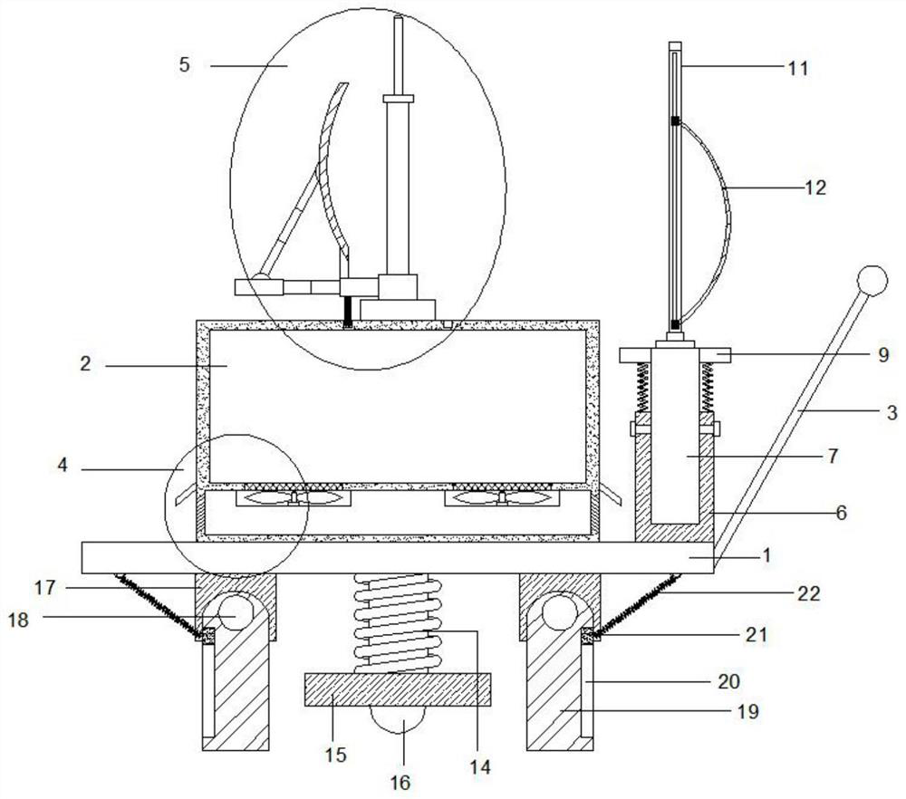
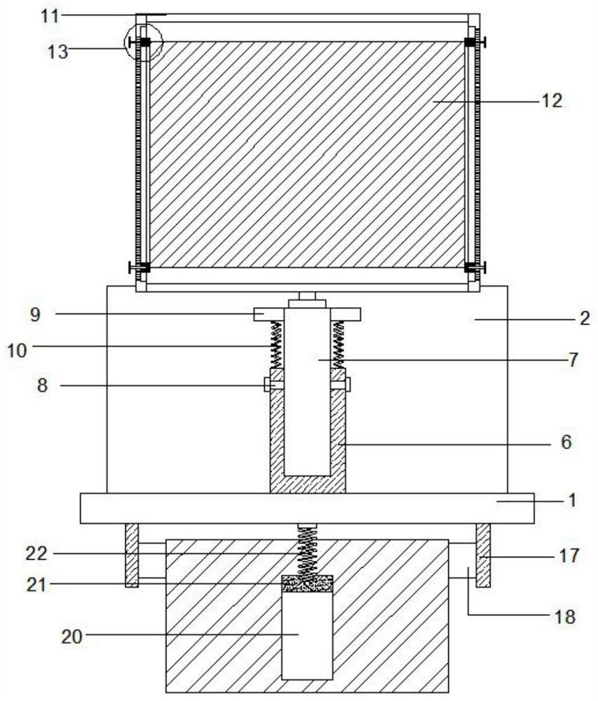
[0029] refer to Figure 1-5 , a mine protector communication wireless transmission device, comprising a base plate 1, a transmission device body 2 disposed above the base plate 1, and a signal strengthening mechanism 5 disposed above the transmission device body 2, the bottom center of the base plate 1 is supported by an elastic column 14 The blocks 15 are connected, the bottom of the support block 15 rotates to connect the roller 16, the upper right side of the bottom plate 1 is connected with a handle 3, the transmission device body 2 is arranged in the center above the bottom plate 1, and a hollow layer 27 is arranged below the transmission device body 2 , both sides of the top of the hollow layer 27 are provided with cooling fans 29, the cooling fans 29 communicate with the interior of the transmission device body 2 through the ventilation net 28, and the side walls on both sides of the hollow layer 27 are provided with a plurality of ventilation holes 30, and the signal is...

Embodiment 2

[0031] Such as Figure 1-5 As shown, this embodiment is basically the same as Embodiment 1. Preferably, the ventilation holes 30 are arranged to incline from the upper part of the hollow layer 27 to the lower part of the transmission device body 2 . While effectively dissipating heat, prevent dust from entering the hollow layer 27 .

[0032] In order to further prevent dust from entering the device, preferably, dust shielding plates 31 are provided on both sides of the exterior of the conveying device body 2 slanting downward, and the dust shielding plates 31 are located directly above the ventilation holes 30 .

Embodiment 3

[0034] Such as Figure 1-3 As shown, this embodiment is basically the same as Embodiment 1. Preferably, a strut 40 is provided under the first connecting plate 33, a circular groove 41 is disposed on the top of the transmission device body 2, and the bottom of the strut 40 is inserted into the circular groove 41 is slidably connected with the bottom of the annular groove 41. The rotation stability of the first connecting plate 33 is effectively improved.

[0035] In order to facilitate the adjustment of the angle of the curved reflector 37, preferably, the end of the first connecting plate 33 away from the rotating block 32 is connected to the second connecting plate 35 through the first telescopic rod 34, and above the second connecting plate 35 It is rotatably connected with the lower end of the second telescopic rod 36 , and the upper end of the second telescopic rod 36 is rotatably connected with the center of the outer side of the arc reflector 37 .


PUM


Abstract

The invention discloses a communication wireless transmission device for a mining protector, and relates to the technical field of communication in mines. The device comprises a bottom plate, a transmission device body and a signal reinforcing mechanism, a hollow layer is arranged below the transmission device body, cooling fans are arranged on the two sides of the top end of the hollow layer, thesignal reinforcing mechanism comprises a rotating block, a first connecting plate and a first antenna, and a second antenna is arranged at the upper end of the first antenna; the upper end of first connecting plate is rotationally connected with an arc-shaped reflecting plate; a sleeve is arranged on the right side of the transmission device body, the bottom of the sleeve is fixed to the bottom plate, the lower end of a supporting rod is inserted into the sleeve and connected with the sleeve through a fixing screw, a mounting frame is arranged at the upper end of the supporting rod, and a flexible reflecting plate is arranged in the mounting frame. The defects in the prior art are overcome, the model receiving strength of the wireless transmission device is effectively improved, the wireless transmission device is convenient to move, multi-angle signal receiving is facilitated, and the use convenience is improved.

Description

technical field [0001] The invention relates to the technical field of mine communication, in particular to a mine protector communication wireless transmission device. Background technique [0002] The wireless transmission device is a device that gets rid of the limitation of the wired network and uses transmission media such as radio waves, microwaves, and infrared rays to transmit files, pictures, and audio to achieve the purpose of information transmission. [0003] At present, the work in the mine also needs to use various wireless transmission devices for information transmission, but because most of the mines are highly sealed and the signal transmission effect is poor, most of the existing wireless transmission devices need to constantly change their positions to determine the signal when they are in use. The best location, but due to the large size of the general mine protector communication wireless transmission device, it is inconvenient to move, and the signal r...

Claims


Application Information

Patent Timeline
Patent Type & Authority Applications(China)
IPC IPC(8): H01Q1/12H01Q15/16H01Q1/00
CPCH01Q1/1264H01Q15/16H01Q1/02
Inventor 谢金龙王球锋谢法金伯彩云闫谨
Owner HEFEI SWITCH FACTORY
Why Eureka
Try Eureka