Anti-electric-shock wiring sheath for antenna erection

An anti-shock and sheath technology, applied in the directions of antenna supports/installation devices, circuits, connections, etc., can solve problems such as electric shocks for staff, and achieve the effects of high safety, strong protection, and fast and convenient wiring.

Pending Publication Date: 2021-03-26
ANHUI HENGNUO ELECTROMECHANICAL SCI & TECH
View PDF0 Cites 0 Cited by
  • Summary
  • Abstract
  • Description
  • Claims
  • Application Information

AI Technical Summary

Problems solved by technology

[0004] The purpose of the present invention is to provide an anti-shock wiring sheath for antenna erection, to solve the problem that the exposed conta

Method used


Image

  • Anti-electric-shock wiring sheath for antenna erection
  • Anti-electric-shock wiring sheath for antenna erection
  • Anti-electric-shock wiring sheath for antenna erection

Examples


Embodiment Construction

[0024] The following will clearly and completely describe the technical solutions in the embodiments of the present invention with reference to the accompanying drawings in the embodiments of the present invention. Obviously, the described embodiments are only some, not all, embodiments of the present invention.

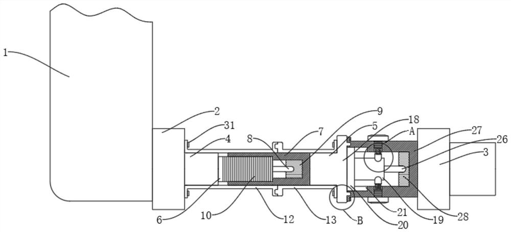
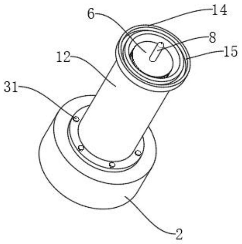
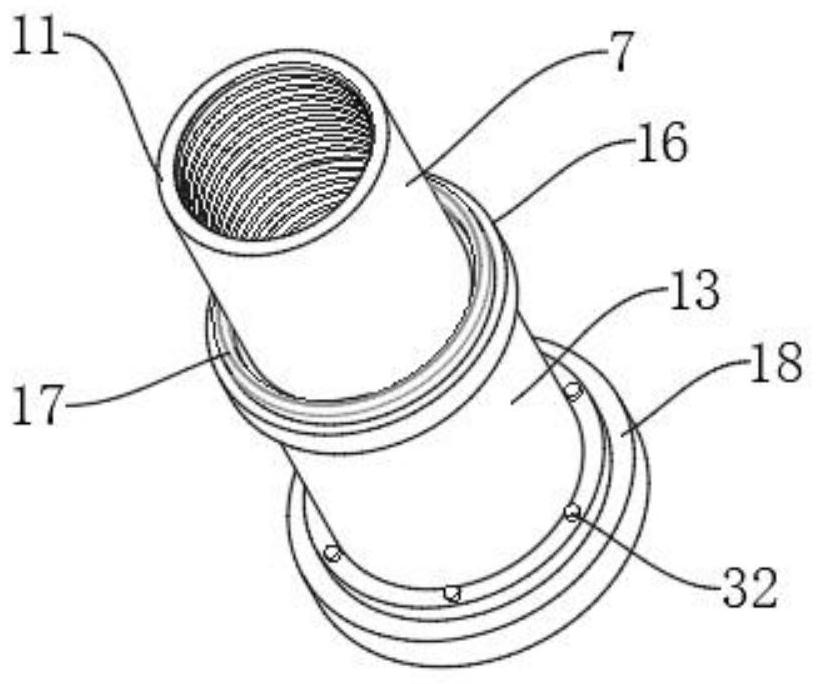
[0025] see Figure 1-5 , an embodiment provided by the present invention: an anti-shock wiring sheath for erecting an antenna, including an antenna main body 1, a first terminal 2 and a second terminal 3, the first terminal 2 is located on the side of the antenna main body 1 On the upper end, one end of the first terminal 2 is provided with a terminal female seat 4, one end of the second terminal 3 is provided with a terminal male head 5, the terminal female seat 4 includes a stud 6, the terminal male head 5 includes a screw sleeve 7, and the screw sleeve The inside of 7 is provided with a first connector 9, the inside of the stud 6 is provided with a first terminal ...


PUM


Abstract

The invention discloses an anti-electric-shock wiring sheath for antenna erection, relates to the technical field of antenna erection, and aims to solve the problem that in the wiring process of an existing antenna, an electric shock accident of a worker is easily caused by an exposed contact. A first connector lug is located at the upper end of an antenna body, a terminal female seat is arrangedat one end of the first connector lug, a terminal male head is arranged at one end of the second connector lug, the terminal female seat comprises a stud, the terminal male head comprises a threaded sleeve, and a first connector is arranged in the threaded sleeve. A first wiring terminal is arranged in the stud, the first wiring terminal is embedded into the first connector, an external thread isarranged on the outer side of the stud, an internal thread is arranged on the inner side of the threaded sleeve, the stud is in threaded connection with the threaded sleeve, and a first wiring sheathis arranged on the outer side of the terminal female seat; and the outer side of the terminal male head is provided with a second wiring sheath.

Description

technical field [0001] The invention relates to the technical field of antenna erection, in particular to an electric shock-proof wiring sheath for antenna erection. Background technique [0002] An antenna is a transformer that transforms a guided wave propagating on a transmission line into an electromagnetic wave propagating in an unbounded medium (usually free space), or vice versa. A component used in radio equipment to transmit or receive electromagnetic waves. Engineering systems such as radio communication, broadcasting, television, radar, navigation, electronic countermeasures, remote sensing, and radio astronomy, which use electromagnetic waves to transmit information, rely on antennas to work. In addition, in terms of using electromagnetic waves to transmit energy, non-signal energy radiation also requires antennas. For the application effect of antennas and to increase the height of mobile communication antennas, antennas need to be erected. [0003] However, d...

Claims


Application Information

Patent Timeline
IPC IPC(8): H01Q1/12H01R13/44H01R13/629H01R13/627H01R13/52H01R13/502H01R24/00
CPCH01Q1/12H01R13/44H01R13/502H01R13/5202H01R13/627H01R13/629H01R24/00
Inventor 王庆虎
Owner ANHUI HENGNUO ELECTROMECHANICAL SCI & TECH
Why Eureka
Try Eureka