Crimping type wiring terminal and use method thereof

A terminal and crimping technology, applied in the field of crimping terminals, can solve the problems of inability to meet space requirements, low reliability, and high cost, achieve a high degree of functional integration of parts, meet the requirements of space limitations, and use Convenient and fast effects

Pending Publication Date: 2021-03-26
CHENGDU RELIANCE ELECTRIC
View PDF0 Cites 2 Cited by
  • Summary
  • Abstract
  • Description
  • Claims
  • Application Information

AI Technical Summary

Problems solved by technology

[0005] One is that the wire needs to be bent and inserted into the terminal wiring hole for connection, which cannot meet the requirements of special working conditions;
[0006] Second, the volume is too large to meet the space requirements;
[0007] Third, the compatible range of terminal wiring is too small, and customers must choose a variety of terminals compatible with the existing wire range, which is not conducive to cost reduction for customers;
[0008] Fourth, it is inconvenient to disengage the terminal, which cannot meet the customer's restrictions on the operating space;
[0009] Fifth, the structure is more complicated, the cost is high, and the reliability is low

Method used


Image

  • Crimping type wiring terminal and use method thereof
  • Crimping type wiring terminal and use method thereof
  • Crimping type wiring terminal and use method thereof

Examples


Embodiment 1

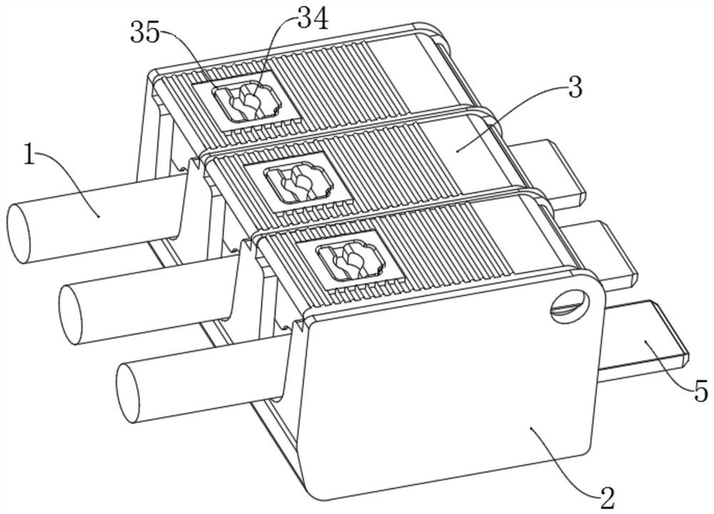
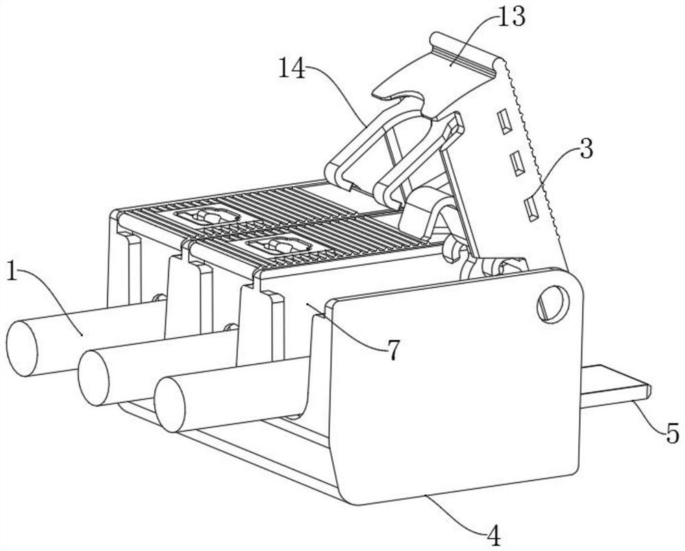
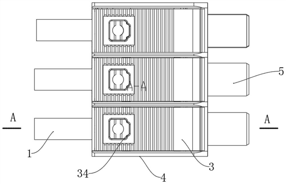
[0066] The invention discloses a crimping type terminal, comprising a base part 2 for installing a wire 1 and a pressing part 3 connected to the base part 2 for pressing the wire 1 on the base part 2; The seat part 2 includes an insulating base 4, a conductive sheet 5 and an end cover 6. The insulating base 4 is provided with at least one installation position 7, and the left end of the installation position 7 is an incoming line end; the installation position 7 is equipped with the conductive sheet 5. The end cover 6 and the pressing part 3, the conductive sheet 5 is fixedly installed in the installation position 7 through the end cover 6, the pressing part 3 is located above the conductive sheet 5 and is hingedly installed in the installation position 7; The tightening part 3 can be engaged with the conductive sheet 5 after being rotated, and the pressing part 3 and the conductive sheet 5 are engaged with each other to press the wire 1 tightly on the conductive sheet 5 .

[...

Embodiment 2

[0092] This embodiment is further optimized on the basis of Embodiment 1. In this embodiment, the pressing part 3 also includes a push block 34, the protective cover 13 is provided with a first push block groove 35, and the horizontal part 15 of the elastic piece 14 A second push block groove 36 is arranged at a position corresponding to the first push block groove 35, and the push block 34 is slidably installed in the first push block groove 35;

[0093]The mounting groove 27 is provided with a protruding bar 37 that can extend into the second push block groove 36; the side wall of the push block 34 is provided with a limit boss 38, and the limit boss 38 has a guide slope, and the push block 34 is slidably installed on the second push block. Once inside the push block groove 35 , the limiting boss 38 on the push block 34 is engaged with the protruding strip 37 ;

[0094] For further optimization, anti-slip lines 39 are provided on the upper end surface of the protective cover...

Embodiment 3

[0100] This embodiment is basically similar to Embodiment 1 or Embodiment 2, the difference is that the first horizontal portion 23 is bent at a right angle, and the bottom of the end cover 6 is provided with a vertical through groove 40 communicating with the positioning groove 9 , the first horizontal portion 23 can pass through the through slot 40 after being bent.

[0101] In order to adapt to different space requirements, one of the tails of the conductive sheet 5 is set to be bent, and the other is set to be not bent, which can be produced by replacing inserts with the same pair of molds. For the end cap 6, only the local features are changed, and the production of inserts can also be replaced by the same secondary mold. In this way, it not only satisfies product changes, but also reduces the mold cost to the greatest extent.


PUM


Abstract

The invention discloses a crimping type wiring terminal. The crimping type wiring terminal comprises a base part used for installing a wire and a pressing part connected to the base part and used forpressing the wire on the base part, wherein the base part includes an insulating base, a conducting strip and an end cover, at least one mounting position is arranged on the insulating base, and the left end of the mounting position is a wire inlet end; the conducting strip, the end cover and the pressing part are arranged in the mounting position in a matched mode, the conducting strip is fixedlyinstalled in the mounting position through the end cover, and the pressing part is located above the conducting strip and installed in the mounting position in a hinged mode; and the pressing part can be buckled with the conducting strip after rotating, and the wire can be tightly pressed on the conducting strip after the pressing part and the conducting strip are buckled with each other. In addition, the invention also discloses a use method of the crimping type wiring terminal. In actual use, the purpose of quickly fixing the wire can be achieved, and the situation that the wire is bent inthe crimping process can be avoided. The terminal has the advantages of simple structure, small size, convenience in use and low cost.

Description

technical field [0001] The invention belongs to the technical field of electric connection, and specifically relates to a crimping type terminal; in addition, the invention also relates to a method for using the crimping type terminal. Background technique [0002] Terminal block is a very important product in the field of electrical connection. Its low cost and flexible application mode make various new technologies and related products of terminal block emerge in an endless stream in the domestic and foreign electric union product market. From the initial plate terminal, to the later crimping frame terminal, to the current shrapnel terminal, no matter how the terminal is upgraded, most of the existing terminals have not made breakthroughs and innovations in the wiring method, that is, they are all assumptions The lead wire of the terminal can be bent, and after the terminal is installed, the lead wire is inserted into the corresponding terminal hole to realize the connecti...

Claims


Application Information

Patent Timeline
Patent Type & Authority Applications(China)
IPC IPC(8): H01R9/24H01R4/48H01R43/00H01R43/26
CPCH01R9/24H01R43/00H01R43/26H01R4/48365H01R4/4809H01R4/489H01R9/2491
Inventor 蒲新明高云旭于滨刘阳刘铭宏程忠
Owner CHENGDU RELIANCE ELECTRIC
Why Eureka
Try Eureka