Equipment for the treatment of the hydraulic braking system of a vehicle

A technology of hydraulic braking and equipment, applied in the field of vehicles, can solve the problems of low utilization rate, single function, insufficient equipment, etc., and achieve the effect of improving utilization rate

Active Publication Date: 2022-08-09
BYD CO LTD
View PDF0 Cites 0 Cited by
  • Summary
  • Abstract
  • Description
  • Claims
  • Application Information

AI Technical Summary

Problems solved by technology

In the related art, there are devices for flushing the pipelines of the hydraulic braking system of rail vehicles. However, these devices are not perfect and need to be improved. For example, the functions of these devices in the related art are single and the utilization rate is low.

Method used


Image

  • Equipment for the treatment of the hydraulic braking system of a vehicle
  • Equipment for the treatment of the hydraulic braking system of a vehicle
  • Equipment for the treatment of the hydraulic braking system of a vehicle

Examples


Embodiment 1

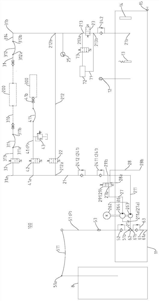
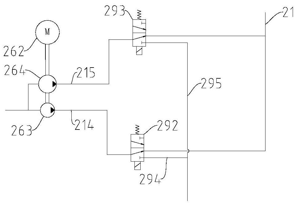
[0123] like Figure 4-Figure 8As shown, the equipment 100 may include: equipment fuel tank 11, main pipeline 21, flushing exhaust pipeline 31, external fueling pipeline 41, internal fueling pipeline 51, switching pipeline 61, detection pipeline 71, and external fuel inlet pipeline 27. Externally connect the oil discharge pipeline 28. The main pipeline 21 includes an oil inlet pipeline section 211, a preset pipeline section 212 and a detection pipeline section 213, which are arranged in sequence along the oil flow direction. A first upstream filter 2411 and a second upstream filter 2412 are arranged between the oil inlet pipeline section 211 and the preset pipeline section 212 , a pressure gauge 25 is arranged between the preset pipeline section 212 and the detection pipeline section 213 , and the detection pipeline section 213 Downstream is provided with a downstream filter 242. The equipment oil tank 11 has a temperature sensor 13 , an air filter 12 , a liquid level gauge 1...

Embodiment 2

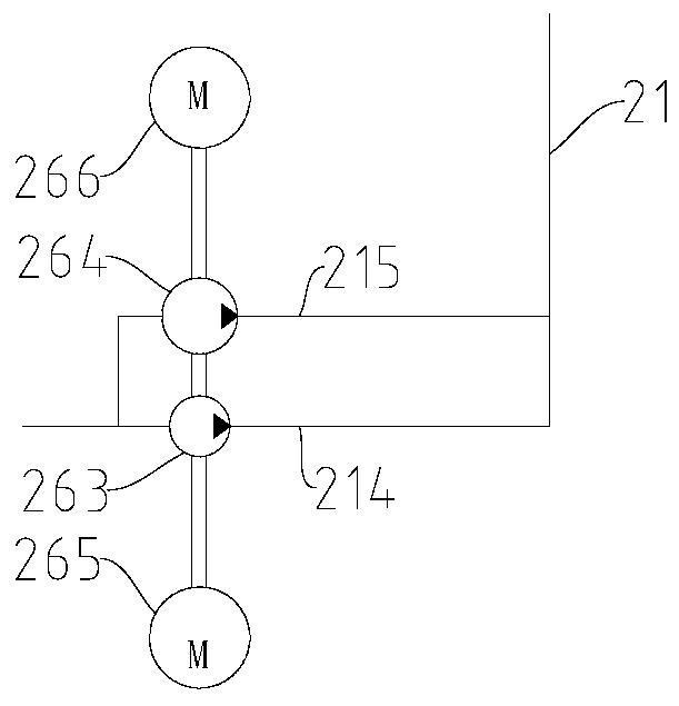
[0144] like Figure 9-Figure 13 As shown in the figure, the second embodiment has the same general structure compared with the above-mentioned first embodiment, and the same reference numerals are used for the same components. Then there is a double pump, so that the external oil inlet pipeline 27 connected in parallel with the oil inlet pipeline section 211 , and the external oil discharge pipeline 28 and the regulating device 29 related to the external oil inlet pipeline 27 can be omitted. (2) The switching device 62 is a manually adjusted direction control cock, and the switching device 53 and the second oil suction filter 52 are canceled on the internal fueling pipeline 51 . (3) The first oil suction filter 63 on the switching line 61 is cancelled, and the third oil suction filter 216 is provided between the inlet end 21 a of the main line 21 and the oil pump 261 . In contrast, the structure of the second embodiment is simpler, lower in cost, and easier to control than th...

Embodiment 3

[0161] like Figure 14-Figure 18 As shown in the figure, the third embodiment has the same general structure compared with the above-mentioned second embodiment, and the same components have the same reference numerals. The third suction filter 216 in between. (2) There is only one upstream filter 241 . (3) The external refueling pipeline 41 is cancelled, and the flushing and exhausting pipeline 31 is a multifunctional pipeline 31A that can be installed with the refueling gun 34, so that the multifunctional pipeline 31A can be used to flush, exhaust and refuel the hydraulic brake system of the vehicle. . (4) Cancel the first overflow valve 43, set the second overflow valve 44 on the multi-function pipeline 31A, set the third overflow valve 45 on the preset pipeline section 212, and set the main pipeline 21 at the preset position One-way valve 217 upstream of line segment 212 . (5) The first on-off valve 22 and the second on-off valve 32 are canceled, and a reversing device...


PUM


Abstract

The invention discloses a device for processing a hydraulic braking system of a vehicle. The device includes an equipment oil tank, a main pipeline, an oil pump device and a control device. The inlet end and the outlet end of the main pipeline are both connected to the equipment oil tank. The oil pumping device includes: a first flow pump and a second flow pump, the flow rate of the first flow pump is smaller than the flow rate of the second flow pump, and both the first flow pump and the second flow pump are used to pump the oil in the oil tank of the equipment into the main pipeline , the control device is used to control the oil intake of the main circuit. According to the device for processing the vehicle hydraulic brake system of the present invention, since the oil pump device includes the first flow pump and the second flow pump, and by setting the regulating device, the oil volume of the main circuit can be regulated, so as to better satisfy the different actual requirements.

Description

technical field [0001] The present invention relates to the technical field of vehicles, in particular to a device for processing a hydraulic braking system of a vehicle. Background technique [0002] Rail vehicles are equipped with a hydraulic braking system. During the production process of rail vehicles, impurities such as burrs are inevitably left in the pipelines of the hydraulic braking system. Therefore, before the rail vehicles leave the factory, the pipelines of the hydraulic braking system need to be cleaned to avoid During the operation of the rail vehicle, it is affected by the impurities in the pipeline of the hydraulic braking system, which causes the operation failure of the rail vehicle. In the related art, there are devices for flushing the pipelines of the hydraulic braking system of the rail vehicle. However, these devices are not perfect and need to be improved. For example, these devices in the related art have single function and low utilization rate. ...

Claims


Application Information

Patent Timeline
Patent Type & Authority Patents(China)
IPC IPC(8): B60T13/66B60T13/68
CPCB60T13/66B60T13/686
Inventor 钟海斌张鑫李道林
Owner BYD CO LTD
Why Eureka
Try Eureka