Wing high-lift device and wing high-lift method

A technology of increasing lift device and wing, which is applied in aircraft parts, aircraft control, transportation and packaging, etc. It can solve the problems of frequent overhaul and maintenance, low efficiency, and increase of lift, and achieve high utilization rate of vibration energy and flexible control mode , to reduce the effect of negative impact

Active Publication Date: 2021-03-30
NAT UNIV OF DEFENSE TECH
View PDF5 Cites 5 Cited by
  • Summary
  • Abstract
  • Description
  • Claims
  • Application Information

AI Technical Summary

Problems solved by technology

While increasing the lift, the mechanical lift device also brings many problems: the moving parts require a complicated and heavy mechanical control system, which is not conducive to reducing the volume and weight of the aircraft; frequent inspection and maintenance are required, which increases the maintenance cost of the aircraft, etc.
At present, the use of circulation control technology to increase lift still faces problems such as low efficiency and inconvenient application. One of the main reasons is the problem of air source

Method used


Image

  • Wing high-lift device and wing high-lift method

Examples


Embodiment Construction

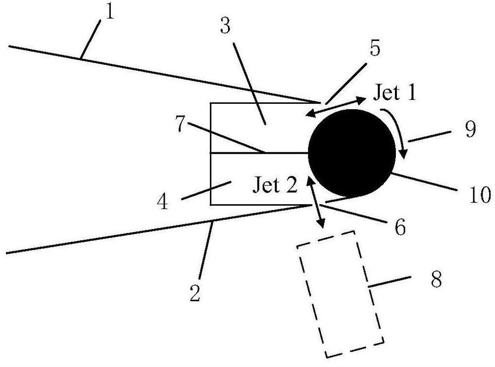
[0021] The technical solutions in the embodiments of the present invention will be clearly and completely described below with reference to the accompanying drawings in the embodiments of the present invention. Obviously, the described embodiments are only a part of the embodiments of the present invention, not all of the embodiments. Based on the embodiments of the present invention, all other embodiments obtained by those of ordinary skill in the art without creative efforts shall fall within the protection scope of the present invention.

[0022] It should be noted that all directional indications (such as up, down, left, right, front, back, etc.) in the embodiments of the present invention are only used to explain the relationship between various components under a certain posture (as shown in the accompanying drawings). The relative positional relationship, the movement situation, etc., if the specific posture changes, the directional indication also changes accordingly. ...


PUM


Abstract

The invention discloses a wing high-lift device and a wing high-lift method. The wing high-lift device comprises a wing upper surface, a wing lower surface, a wing rear edge and a wing high-lift structure, wherein the wing high-lift structure comprises a first jet cavity and a second jet cavity arranged between the wing upper surface and the wing lower surface, the isolation plate is arranged between the first jet flow cavity and the second jet flow cavity; the wing lift augmentation structure further comprises a first jet flow opening and a second jet flow opening which are formed in the rearedge of the wing, the first jet flow opening communicates with the first jet flow cavity, the second jet flow opening communicates with the second jet flow cavity, the first jet flow cavity is located between the upper surface of the wing and the isolation plate, and the second jet flow cavity is located between the lower surface of the wing and the isolation plate; and therefore, the structure of the synthetic double-jet exciter is formed. Based on the double effects of the Coanda effect and the virtual trailing edge flap generated by the synthetic double-jet technology, the traditional circular rector lift augmentation technology and the virtual trailing edge flap effect are combined, the purpose of lift augmentation is achieved, and the lift augmentation efficiency of the traditional circular rector lift augmentation technology is improved.

Description

technical field [0001] The invention relates to the technical field of active flow control, in particular to a wing lift device and a wing lift method. Background technique [0002] At present, the new generation of aircraft has taken ultra-short take-off and landing, no control surface manipulation, etc. as important performance indicators. As the main means to help achieve high-performance indicators, increased lift technology has increasingly attracted widespread attention and research. [0003] Currently widely used wing lift devices mainly include mechanical moving parts such as flaps, slats, and multi-section wings. While increasing the lift, the mechanical lift device also brings many problems: the moving parts require a complex and heavy mechanical control system, which is not conducive to reducing the size and weight of the aircraft; it requires frequent overhaul and maintenance, which increases the maintenance cost of the aircraft. To avoid the above problems, it ...

Claims


Application Information

Patent Timeline
Patent Type & Authority Applications(China)
IPC IPC(8): B64C21/04
CPCB64C21/04Y02T50/10
Inventor 罗振兵李石清刘强刘志勇
Owner NAT UNIV OF DEFENSE TECH
Why Eureka
Try Eureka