Pneumatic device for intravenous infusion

A drip and air pressure technology, applied in the direction of pressure infusion, the introduction of instruments into the body, etc., can solve the problems of inconvenience, sitting on the bed or chair, etc., and achieve the effect of easy replacement, convenient portability and good safety

Inactive Publication Date: 2010-12-15
崔浩 +1
View PDF5 Cites 0 Cited by
  • Summary
  • Abstract
  • Description
  • Claims
  • Application Information

AI Technical Summary

Problems solved by technology

[0003] The purpose of the present invention is to solve the problem of the existing intravenous drip, which requires a hanging bottle bracket to hang the infusion bottle. Some modern hospitals have buried the suspension for hanging the infusion bottle on the ceiling of the sick room in advance. to sit on a bed or chair
It is very inconvenient for patients who need to be active, providing an air pressure device for intravenous drip

Method used


Image

  • Pneumatic device for intravenous infusion
  • Pneumatic device for intravenous infusion
  • Pneumatic device for intravenous infusion

Examples


specific Embodiment approach 1

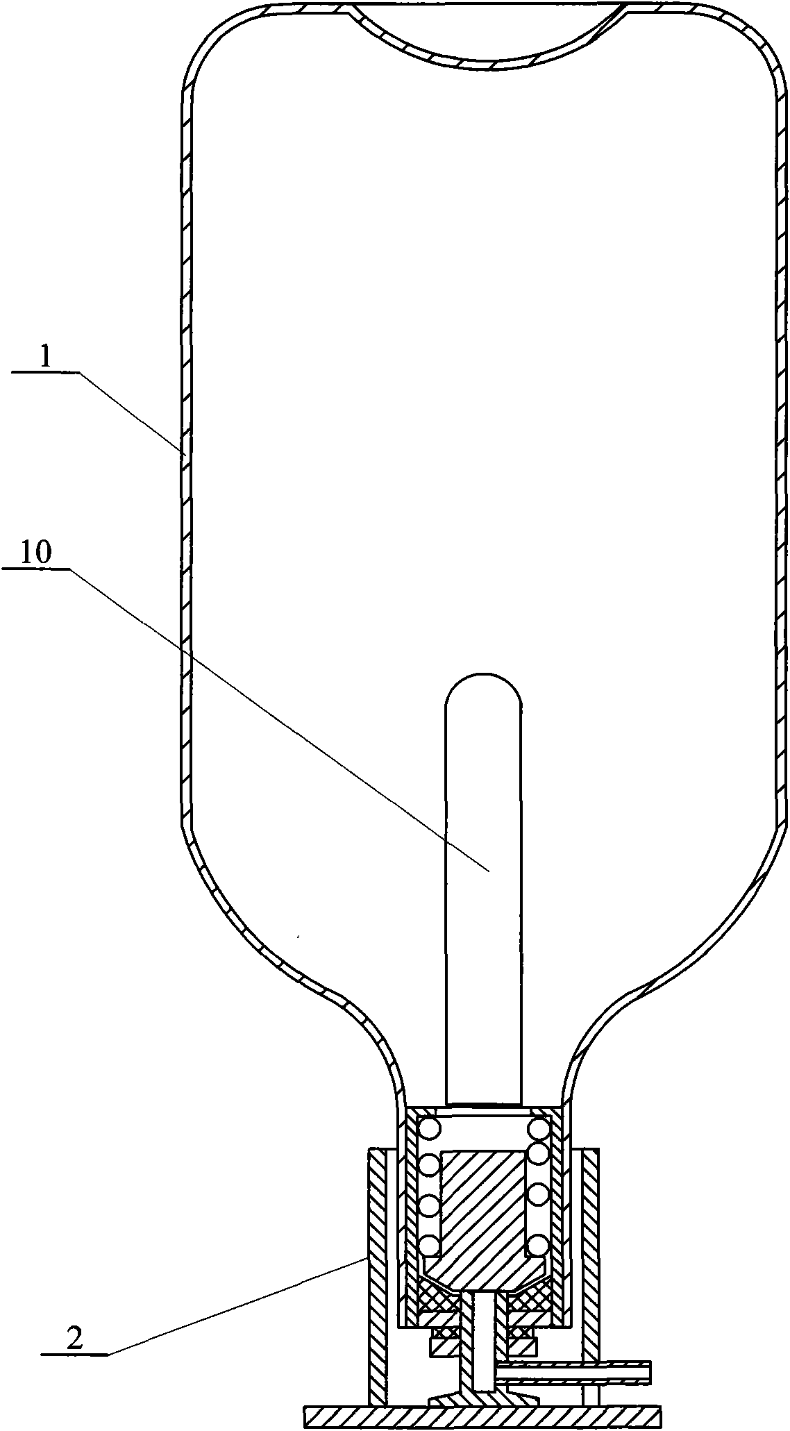
[0015] Specific implementation mode 1: Combination Figure 1 ~ Figure 3 To describe this embodiment, this embodiment includes a gas storage tank body 1 and an air outlet nozzle 2, and the gas storage tank body 1 and the air outlet nozzle 2 are screwed or inserted.

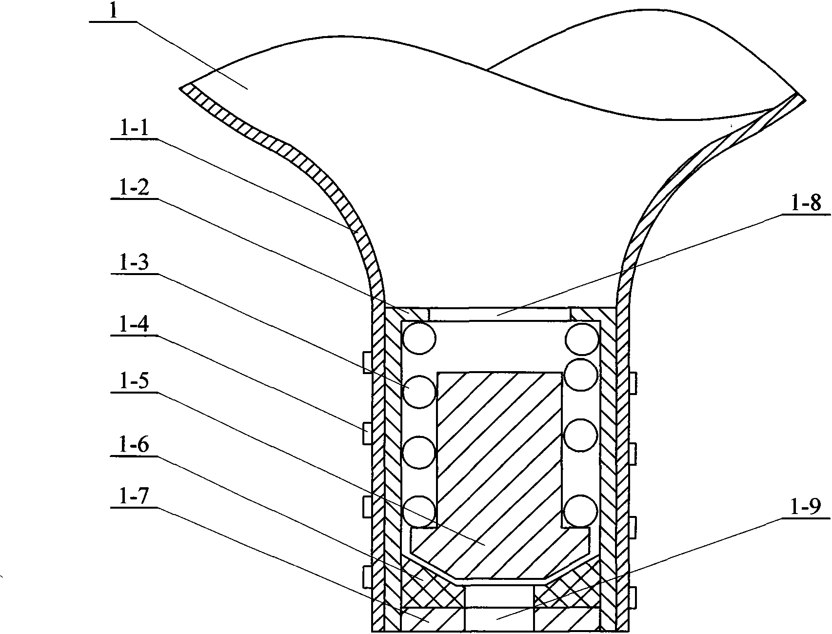
[0016] The gas storage tank body 1 includes a tank body 1-1, a spring seat 1-2, a spring 1-3, a plug 1-5, a gasket 1-6, and a tank mouth stopper 1-7. The spring seat 1-2 is fixed on the tank In the can mouth of the body 1-1, the spring 1-3 and the plug 1-5 are arranged in the spring seat 1-2, the can mouth stopper 1-7 is fixed on the outermost end of the spring seat 1-2, and the sealing gasket 1- 6 is fixed on the inner side of the can mouth baffle 1-7, the sealing gasket 1-6 is matched with the plug 1-5, and the outer side of the can body 1-1 is provided with an external thread 1-4.

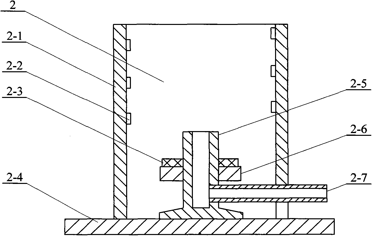
[0017] The air outlet 2 includes a cylinder 2-1, a plastic cushion 2-3, a base 2-4, a top valve 2-5, a plastic cushion seat 2-6 and an a...

specific Embodiment approach 2

[0018] Specific implementation manner two: combination Figure 7 To describe this embodiment, the gas tank body 1 of this embodiment includes a tank body 1-1, a stop 1-11, a check valve body 1-12, a check valve spring 1-13, and a glass ball 1-14 , Tank cover 1-16 and sealing ring 1-17, tank cover 1-16 and tank mouth of tank body 1-1 are screwed together, there will be a check valve between tank cover 1-16 and tank mouth of tank body 1-1 The bottom edge 1-18 of the valve body 1-12 is clamped, and the bottom edge 1-18 of the valve body 1-12 of the one-way valve is provided with a sealing ring 1-17 between the mouth of the tank 1-1 The valve spring 1-13 and the glass ball 1-14 are arranged in the valve body 1-12 of the one-way valve, and the stop 1-11 is fixed on the upper end of the valve body 1-12 of the one-way valve. Vent holes 1-15 are opened on 1-12.

[0019] The air outlet 2 includes a vent pipe 2-12, a sealing ring 2-13, a bracket 2-14, a non-reverse claw 2-15, and a vent p...

specific Embodiment approach 3

[0021] Specific implementation mode three: combination figure 1 with Figure 7 To explain this embodiment, this embodiment also includes a pressure indicator 10, which is arranged in the tank body 1-1. The pressure indicator 10 is composed of a transparent tube 10-1 and a piston 10-2, and the piston 10-2 is arranged in the transparent tube. In 10-1, a scale is provided on the outer surface of the transparent tube 10-1. The tank body 1-1 can be made of plastic. The pressure indicator 10 is fixed in the tank body 1-1. After the tank body 1-1 is inflated, the pressure inside the tank body 1-1 increases, causing the piston 10-2 to move inward. Push forward, otherwise exit outward. The scale on the front of the piston is the pressure value in the tank. Others are the same as the first or second embodiment.


PUM


Abstract

The invention discloses a pneumatic device for intravenous infusion, relates to a pneumatic device and aims to solve the problems that the conventional intravenous infusion needs an infusion bottle bracket for hanging an infusion bottle, which is inconvenient for a patient who needs to move. A spring and a plug are arranged inside a spring seat; an opening baffle sheet is fixed at the outermost end of the spring seat; and a sealing gasket is fixed on the inner side of the opening baffle sheet and is matched with the plug. A cylinder is fixed on a base; an overhead valve is fixed on the base inside the cylinder; a plastic gasket base is fixed on an outer wall of the overhead valve; a plastic gasket is arranged on the plastic gasket base; one end of an air outlet adapter is communicated with the overhead valve; internal threads are formed on an inner wall of the cylinder; and the internal threads of the cylinder are matched with external threads of a tank body. The pneumatic device has the inflation pressure of 0.6 to 1 MPa and the inflation capacity of 500 to 600 cubic centimeters, can be used for 2,000ml of liquid medicine for intravenous infusion, and has the advantages of convenient carrying, high safety, easy disinfection and convenient replacement.

Description

Technical field [0001] The invention relates to a pneumatic device. Background technique [0002] The current intravenous drip requires a hanging bottle holder to hang the infusion bottle. Some modern hospitals have pre-installed a suspension for hanging the infusion bottle on the ceiling of the ward. Patients often have to sit on a bed or chair during infusion. on. It is very inconvenient for patients who need to move. It is convenient and convenient to go to the bathroom, eat in the dining room, take a walk in the hospital, etc. You can often see someone holding a bottle to accompany the patient in and out. For severe patients, patients who need to replenish a large amount of liquid medicine in time, in order to ensure the pressure of the infusion, it is often necessary to raise the infusion bottle on the hanging bottle holder to obtain a faster infusion rate. In recent years, someone invented a pressurized infusion device to replace the bottle holder, but due to many problem...

Claims


Application Information

Patent Timeline
IPC IPC(8): A61M5/155
Inventor 崔浩周四骏
Owner 崔浩
Why Eureka
Try Eureka