Platform system for transformer installation

A transformer and platform technology, applied in the field of transformers, can solve problems such as power outages, affecting the living needs of surrounding residents, and the inability to maintain a safe distance between high-voltage and low-voltage wiring harnesses, and achieve the effects of convenient construction, avoiding falling from high altitudes, and convenient assembly

Inactive Publication Date: 2021-03-30
四川精点企业管理有限公司
View PDF0 Cites 1 Cited by
  • Summary
  • Abstract
  • Description
  • Claims
  • Application Information

AI Technical Summary

Problems solved by technology

[0004] The technical problem to be solved by the present invention is that the existing transformer installation mainly uses a crane for hoisting construction, but since the power transformer is in the process of replacement and maintenance operations, there are usually high-voltage wire harnesses and low-voltage wire harnesses that are normally operating above the tower. , the boom of the crane cannot keep a safe distance from the high-voltage wire harness and the low-voltage wire harness during the stretching and hoisting process, resulting in a power outage during the construction process for normal construction, which seriously affects the living needs of the surrounding residents

Method used


Image

  • Platform system for transformer installation
  • Platform system for transformer installation
  • Platform system for transformer installation

Examples


Embodiment 1

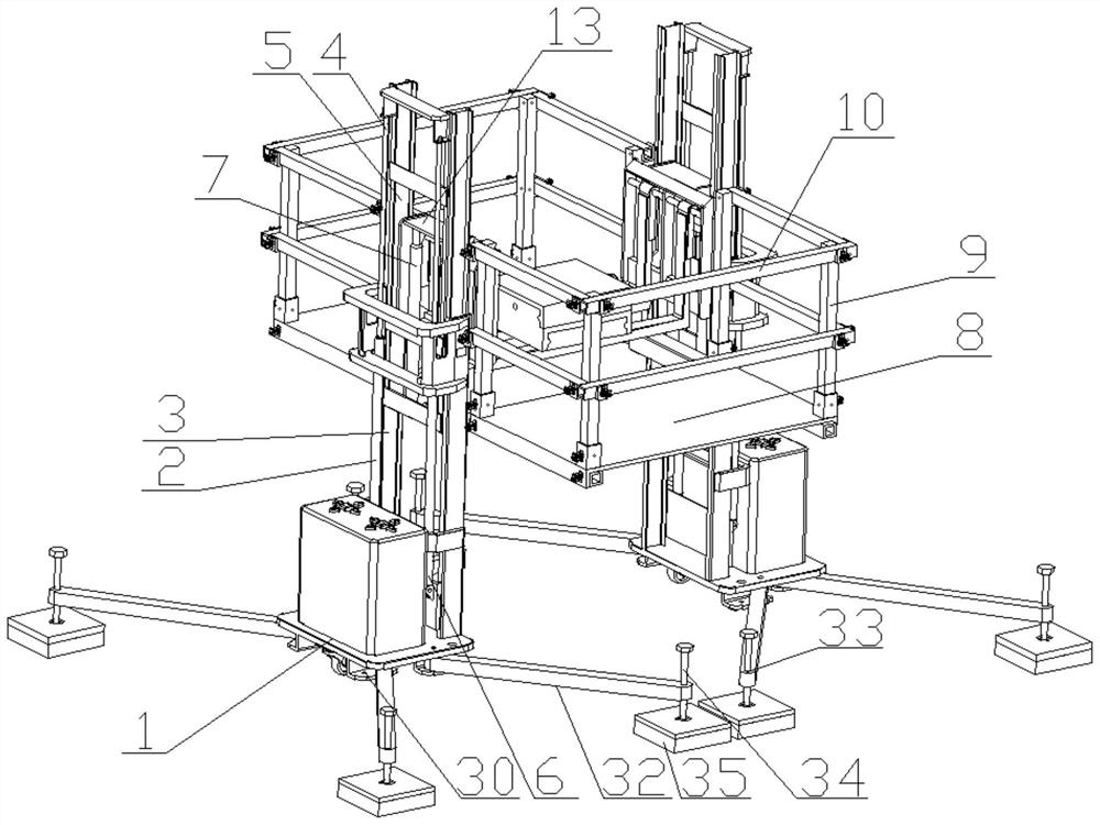
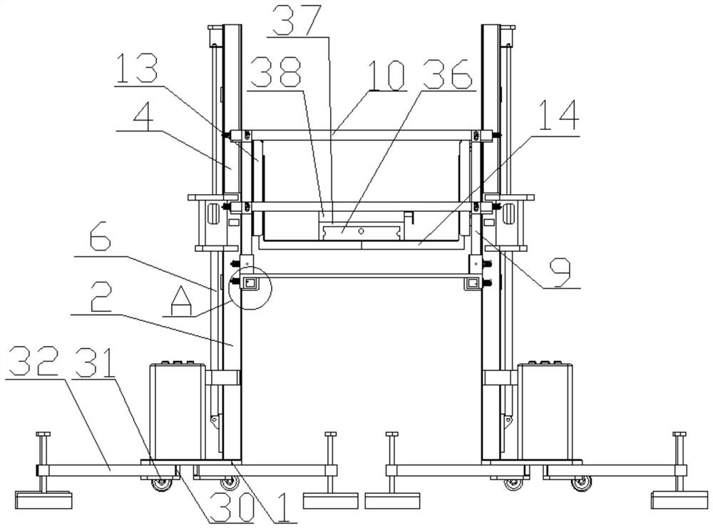
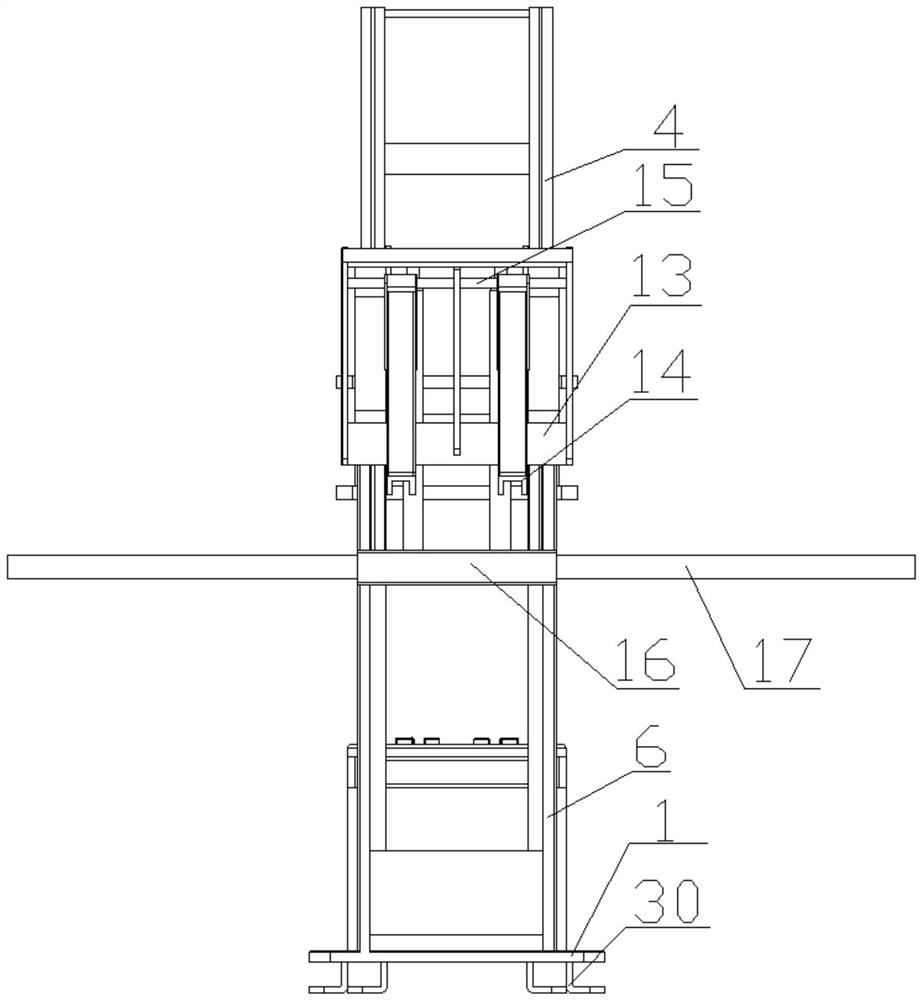
[0037]Such asFigure 1-10As shown, the platform system for the transformer is mounted, including the first lifting device, the second lifting device, the construction platform portion, wherein the first lifting device and the second lifting device are symmetrical, the first lifting device and the The second lifting device includes a base 1, a support post 2 disposed on the base 1, and the support post 2 has two, and the two of the support post 2 is concave in the side wall of the support column 2, the first slide groove 3, A rectangular frame 4 is provided in the first slide 3, the rectangular frame 4 and the opposite surface of the two edges parallel to the support post 2, and a transformer is provided in the second chute 5. The first hydraulic telescopic cylinder 6 is provided between the support column 2 and the rectangular frame 4, the first hydraulic telescopic cylinder 6 telescoping the rectangular frame 4 to move along the first slide 3, A second hydraulic telescopic cylinder ...

Embodiment 2

[0039]Such asFigure 1-10As shown, the present embodiment is substantially identical to the first embodiment, and the difference is therefore, further comprising a fastening device, both sides of the bottom plate 8 are provided with a flange 18, the fastening device to pass the flange 18 The bottom plate 8 is relatively opposite to the crossbar 17, and the mounting seat 12 is in-shaped structure, and one end of the mounting seat 12 is fixed to the column 9, and the mounting seat 12 is provided with a fastening device. The fastening device can secure the column 9 to the outer rod 10, and the sidewall of the jack 11 is provided with a fastening device, and the fastening means can secure the bottom plate 8 to the column 9. The fastening device includes a fixing plate 19, a U-shaped block 20, a plug, and a spring 21, and both ends of the U-shaped block 20 are connected to the fixing plate 19, and the U-shaped block 20 and the fixed plate 19 are arranged throughout Head, the latop is inse...

Embodiment 3

[0041]Such asFigure 1-10As shown, the present embodiment is substantially the same as that of Example 2, and the difference is that the bottom portion of the first lifting device and the second lifting device is provided with a tab 30 and a universal wheel assembly 31, and the mounting end 30 The support rod 32 is rotated, and the support rod 32 is provided with a second threaded hole 33 away from one end of the mounting tab 30, and the second threaded hole 33 is provided with a thread 34, the thread 34 away from the transformer. One end of the lifting portion is hinged by a ball 35. Also included with a two-dimensional platform, the two-dimensional platform is disposed at the top of the fork teeth 14 including a fixed stage 36, a first mobile station 37, a second mobile station 38, a first driving screw 39 The second driving rod 40, the bottom of the first mobile station 37 is provided with a first tab, the first connection, and a first threaded through hole, and both ends of the f...


PUM


Abstract

The invention discloses a platform system for transformer installation. The platform system is characterized in that a first lifting device and a second lifting device are symmetrically arranged, eachof the first lifting device and the second lifting device comprises a base and two supporting columns arranged on the base, the opposite side walls of the two supporting columns are concave inwards to form first sliding grooves, rectangular frames are arranged in the first sliding grooves, the faces opposite to two edges, parallel to the supporting columns, of the rectangular frames are concave inwards to form second sliding grooves, transformer lifting parts are arranged in the second sliding grooves, first hydraulic telescopic cylinders are arranged between the supporting columns and the rectangular frames, and second hydraulic telescopic cylinders are arranged between the rectangular frames and the transformer lifting parts; and insertion holes are formed in a bottom plate, stand columns are detachably inserted into the insertion holes, installation bases are arranged on the stand columns, surrounding rods are installed on the installation bases, one end of the bottom plate is detachably connected with the first lifting device, and the other end of the bottom plate is detachably connected with the second lifting device. The device is convenient to build, and a construction platform is arranged, so that the work is safe.

Description

Technical field[0001]The present invention relates to the field of transformer, and more particularly to a platform system for transformer mounting.Background technique[0002]The transformer is a device that utilizes electromagnetic induction to change the alternating current voltage, and the main components are primary coils, secondary coils, and core. The main function is to achieve voltage conversion, current transform, impedance transformation, isolation, regulator, etc. According to the purpose, it can be divided into power transformers and special transformers; 100 ~ 400 kVA power transformers, using double columnar transformers. The double column transformer is formed by a main rod and a sub-rod, and the bodes are clamped, i.e., the socket of the mounting transformer is formed. The vertical distance from the bottom of the seat should not be less than 2.5 meters, typically 2.5 to 3 meters; the ratio of the height difference between the two ends of the body and the horizontal di...

Claims


Application Information

Patent Timeline
Patent Type & Authority Applications(China)
IPC IPC(8): B66F7/16B66F7/28
CPCB66F7/16B66F7/28
Inventor 李凤英
Owner 四川精点企业管理有限公司
Why Eureka
Try Eureka