Rapid wall decoration method

A fast, wall-mounting technique for use in floors, cladding/linings, construction, etc.

Inactive Publication Date: 2021-03-30
和湜(上海)建筑科技有限公司
View PDF9 Cites 1 Cited by
  • Summary
  • Abstract
  • Description
  • Claims
  • Application Information

AI Technical Summary

Problems solved by technology

[0006] The purpose of the present invention is to solve the existing problems of how to reduce the difficulty of wall decoration and simplify the steps of wall decoration, so as to realize fast wall decoration

Method used


Image

  • Rapid wall decoration method
  • Rapid wall decoration method
  • Rapid wall decoration method

Examples


Embodiment 1

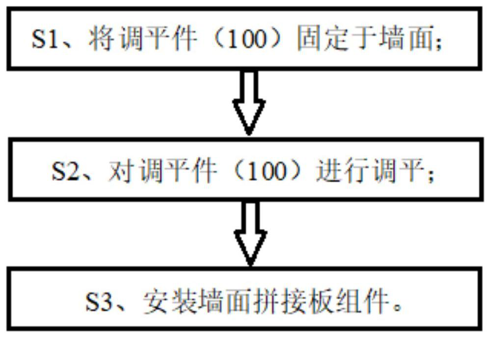
[0057] Refer to attached figure 1 , attached figure 2 , attached image 3 , attached Figure 6 And attached Figure 7 , the present embodiment provides a technical solution: a method for fast wall decoration includes the following steps:

[0058] S1. Fix the leveling member 100 on the wall;

[0059] S2, leveling the leveling member 100;

[0060] S3. Install the wall splicing board assembly.

[0061] Through the above steps, the wall splicing plate assembly can be quickly installed on the uneven wall surface, and the steps are simple and convenient for workers to operate, which is beneficial to reduce the difficulty of construction and shorten the construction period.

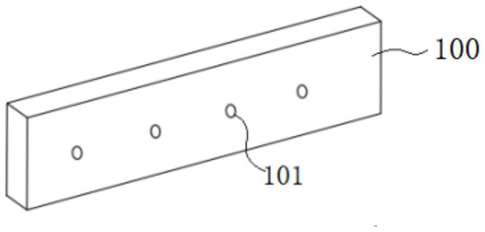
[0062] In a preferred solution, the leveling member 100 is arranged in the shape of a long plate, and the leveling member 100 is provided with several fixing holes 101 .

[0063] In a preferred solution, the step S1 includes the following steps:

[0064] S11. Place the leveling member 100 at a set posit...

Embodiment 2

[0086] Refer to attached Figure 2-5 , the basic structure of this embodiment is the same as that of Embodiment 1, the difference is:

[0087] In a preferred solution, step S2.1 is further included between the step S2 and the step S3, installing the base layer panel 200, and the step S3 is installing a wall splicing panel assembly on the base layer panel 200. The base layer panel 200 is made of lightweight, waterproof and high-strength materials, such as PVC composite board.

[0088] In a preferred solution, said step S2.1 includes the following steps:

[0089] S2.11. Apply fixing glue on the center of the back of the base layer panel 200, the fixing glue is made of materials such as foaming agent, structural glue, putty or marble glue;

[0090] S2.12, set the edge of the base layer panel 200 on the leveling member 100, and at the same time make the fixing glue adhere to the wall surface, so as to realize the fixing glue filling in the gap formed between the base layer panel...

Embodiment 3

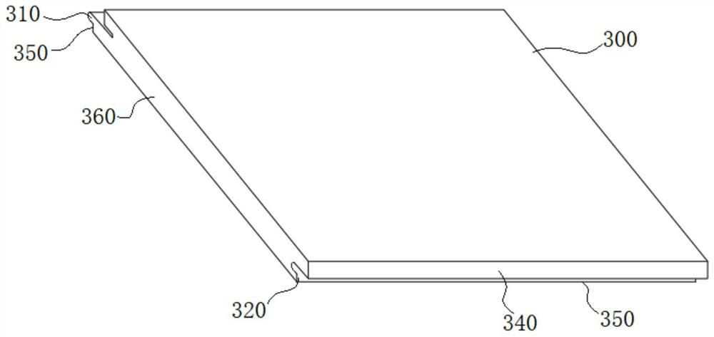
[0096] Refer to attached Figure 7 , the basic structure of this embodiment is the same as that of Embodiment 1, the difference is:

[0097] In a preferred solution, a step S33.1 is set between the step S33 and the step S34, snapping the beautification strip 301 into the fixed surface 350 of the above-mentioned splicing board 300; making the splicing surfaces of the two splicing boards 300 pass through The beauty seams 301 are connected to achieve the effect of beautifying the gap between the splicing surfaces of the two splicing panels 300, and improve the aesthetic effect of the splicing panels 300 after installation.


PUM


Abstract

The invention relates to the technical field of indoor decoration, in particular to a rapid wall surface decoration method. The decoration method comprises the following steps: S1, a leveling piece isfixed to a wall surface; S2, the leveling piece is leveled; and S3, a wall surface splice plate assembly is installed. The installation steps of a wall splicing plate are simple, the advantages thatcement mortar wet operation is not needed, the construction difficulty is low, the construction period is short, and the decoration effect is good are achieved, meanwhile, the modular splicing mode isadopted, and the advantage that the wall surface splicing plate is convenient to dismantle and install is achieved.

Description

technical field [0001] The invention belongs to the technical field of interior decoration, in particular to a method for fast wall decoration. Background technique [0002] At present, the installation process of the wallboard on the wall is complicated, the installation period is long, the required cost is relatively high, and modular installation cannot be performed. [0003] In response to the above problems, after searching, the Chinese invention patent: a prefabricated ceramic tile wall and its construction method (application number is 201910296321.3, and the application date is 2019.6.18), this application discloses a prefabricated ceramic tile wall and its construction method. The construction method includes a main keel installed on the wall on the inner surface and a plurality of tile formworks installed outside the main keel, a plurality of load-bearing keels are equidistantly arranged on the main keel, and the load-bearing keels are arranged parallel to the grou...

Claims


Application Information

Patent Timeline
Patent Type & Authority Applications(China)
IPC IPC(8): E04F13/072E04F13/075E04F13/076E04F13/22E04F13/23
CPCE04F13/072E04F13/0803E04F13/0805E04F13/0807E04F13/081E04F13/0875E04F13/0889E04F13/0891E04F13/0894E04F2201/02E04F2290/04
Inventor 张引强
Owner 和湜(上海)建筑科技有限公司
Why Eureka
Try Eureka