Slurry pipe extension system and construction method thereof

A mud pipe and mud technology, which is used in earth-moving drilling, mining equipment, tunnels, etc., can solve problems such as difficulty in extending mud pipes, and achieve the effect of saving space and ensuring liquid level.

Active Publication Date: 2021-03-30
CHINA RAILWAY ENGINEERING EQUIPMENT GROUP CO LTD
View PDF5 Cites 1 Cited by
  • Summary
  • Abstract
  • Description
  • Claims
  • Application Information

AI Technical Summary

Problems solved by technology

[0005] In view of the deficiencies in the above-mentioned background technology, the present invention proposes a mud pipe extension system and its construction method, which solves the technical problem that the mud pipe is difficult to extend when the existing roadheader is separated.

Method used


Image

  • Slurry pipe extension system and construction method thereof
  • Slurry pipe extension system and construction method thereof
  • Slurry pipe extension system and construction method thereof

Examples


Embodiment 1

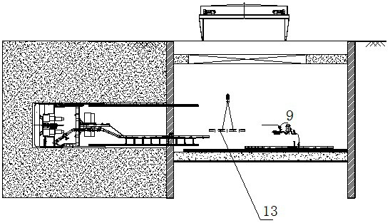
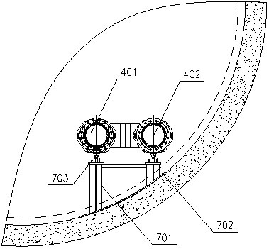
[0045] Example 1, a mud tube extension system, such as Figure 1 - Figure 4 As shown, the punching line and slurry line between the main mud line 101 connected to the motor main unit, including the mud line and the slurry line, including the arrangement in the originating well. The extended hose 8 connected to the mud station, extension of the extended hose 8 extends in the originated well, the extension hose 8 is connected to the host mud pipe 10 by the traveling mud tube 4, and the walking mud hard tube 4 includes walking The feed hard tube 401 and the walking slurry 402.

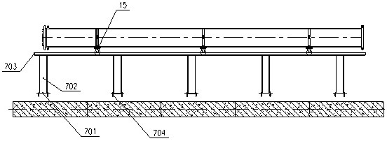
[0046] Such as Figure 5 - Figure 8 As shown, the walking mud hard tube 4 is connected to the traveling unit 15, and the guide bracket 7 of the support travel unit 15 is provided in the originating guide hole, and the motor 1 can be conveniently driven by the guide bracket 7 and the traveling unit 15. The hard tube 4 moves forward, and then the collapsed extended hose 8 is elongated, and the walking mud tube 4...

Embodiment 2

[0051] Example 2, a construction method of a mud tube extension system when a mud water balancing digging machine split is initiated, and the principle is Figure 9 As shown, the construction steps are as follows:

[0052] S1: Put the machine 1, fix the mud tube 11, the slurry unit 9, the extension hose 8, the walking mud hard tube 4, the travel unit 15, the guide bracket 7 complete the underlying surface and complete the installation, according to the length of the extension hose 8 State position one and a predetermined position 2, and the extension hose 8 is located in a predetermined position.

[0053] S2: Open the mud ball valve 6, the first gate valve 10, the second gate valve 16, and closes the ball valve 12, so that the mud stop of the mud station flows into the main chamber of the motor main unit, and when the main chamber mud meets the tunneling requirements of the mud water balance, Start excavation.

[0054] S3: When the extension hose 8 extends to a predetermined posit...

Embodiment 3

[0059] Example 3, a construction method of the mud tube extension system when the mud water balancing digging machine split is initiated, when the earthygo is stopped during the initial time, if the facade is not satisfied, open the punching line The second gate valve 16 turns off the first gate valve 10, opening the ball valve 12 between the sealing unit 9 and the puncturing line, and replenishes the mud to the gas tank, maintaining the facial level of the palm.

[0060] The structure of this embodiment is the same as in Example 1.

[0061] The other steps of the present embodiment are the same as in Example 2.


PUM


Abstract

The invention discloses a slurry pipe extension system and a construction method thereof. The slurry pipe extension system and the construction method thereof solve the technical problem that a slurrypipe is difficult to extend when an existing heading machine starts in a split mode. The slurry pipe extension system comprises a main machine slurry pipeline which is connected with a main machine of the heading machine, and further comprises a slurry feeding pipeline and a slurry discharging pipeline which are connected between slurry stations; each of the slurry feeding pipeline and the slurrydischarging pipeline comprises an extension hose which is arranged in a starting well and connected with the slurry station, and the extension hose is arranged in the starting well in a folded mode before extending; and the extension hose is connected with the main machine slurry pipeline through a travelling slurry hard pipe, the travelling slurry hard pipe is connected with a travelling unit, aguide support for supporting the travelling unit is arranged in a starting pilot tunnel, and after the extension hose extends, the travelling slurry hard pipe is connected with the extension hard pipe. According to the slurry pipe extension system and the construction method thereof, the problems of advancing and extending of the slurry pipeline when a main machine starts and discharging of slurry in the slurry feeding pipe and the slurry discharging pipe when the pipeline extends are solved, and meanwhile the stability of the liquid level of a tunnel face is guaranteed.

Description

Technical field [0001] The present invention relates to the field of mud pipeline extension techniques for the excavator, in particular to a mud tube extension system and a construction method thereof. Background technique [0002] With the diversification of urban underground space development and shield tunnel construction, the impact of the tunnel type, construction conditions, costs, etc., leading to increasing tunnel excavation projects that cannot meet the requirements of Shield machine More needle deployment schemes, especially the originating wells only satisfy the heads of the host, and the post-supporting system needs to be arranged on the well. [0003] When the split is initiated, the main unit and the post-supporting hydraulic, electrical, fluid lines are smaller than the size, and the weight can be pulled directly from the host and follow the host. As the application announced that the date is 2020.05.12. , Connect the bridge, 1 # trolley and 2 # trolley underwater ...

Claims


Application Information

Patent Timeline
Patent Type & Authority Applications(China)
IPC IPC(8): E21D9/06
CPCE21D9/06
Inventor 赵雅琨冯志鹏贾金建任丽娜
Owner CHINA RAILWAY ENGINEERING EQUIPMENT GROUP CO LTD
Why Eureka
Try Eureka