A mud pipe extension system and its construction method

A mud pipe and mud technology, which is used in earth-moving drilling, mining equipment, tunnels, etc., can solve problems such as difficulty in extending mud pipes, and achieve the effect of saving space and ensuring liquid level.

Active Publication Date: 2022-03-29
CHINA RAILWAY ENGINEERING EQUIPMENT GROUP CO LTD
View PDF5 Cites 0 Cited by
  • Summary
  • Abstract
  • Description
  • Claims
  • Application Information

AI Technical Summary

Problems solved by technology

[0005] In view of the deficiencies in the above-mentioned background technology, the present invention proposes a mud pipe extension system and its construction method, which solves the technical problem that the mud pipe is difficult to extend when the existing roadheader is separated.

Method used


Image

  • A mud pipe extension system and its construction method
  • A mud pipe extension system and its construction method
  • A mud pipe extension system and its construction method

Examples


Embodiment 1

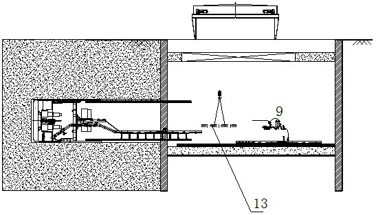
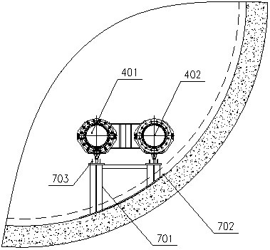
[0045] Embodiment 1, a mud pipe extension system, such as Figure 1-Figure 4 As shown, it includes a slurry inlet pipeline and a slurry discharge pipeline connected between the main engine mud pipeline 101 of the roadheader main engine 1 and the mud station, and the slurry inlet pipeline and the slurry discharge pipeline are both included in the originating well. The extension hose 8 connected to the mud station, before extending, the extension hose 8 is discharged in a folded shape in the originating shaft, and the extension hose 8 is connected with the main engine mud pipeline 101 through the walking mud hard pipe 4, and the walking mud hard pipe 4 includes the walking mud pipe 4 A pulp feeding hard pipe 401 and a walking pulp discharging hard pipe 402.

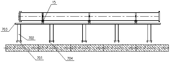
[0046] like Figure 5-Figure 8 As shown, the walking mud hard pipe 4 is connected with a walking unit 15, and a guide bracket 7 supporting the walking unit 15 is arranged in the starting guide tunnel. Hard pipe 4 moves fo...

Embodiment 2

[0051] Embodiment 2, a construction method of the mud pipe extension system when the split body of the mud-water balance roadheader starts, its principle is as follows Figure 9 As shown, the construction steps are as follows:

[0052] S1: The main machine 1 of the roadheader, the fixed mud pipe 11, the slurry collection unit 9, the extension hose 8, the walking mud hard pipe 4, the walking unit 15, and the guide bracket 7 have been lowered into the well and installed, and calibrated according to the length of the extension hose 8 Set position one and set position two, and make the extension hose 8 be located at set position one.

[0053] S2: Open the mud ball valve 6, the first gate valve 10, and the second gate valve 16, and close the ball valve 12 at the same time, so that the mud in the mud station flows into the main engine cabin of the main engine 1 of the roadheader. When the mud in the main engine cabin meets the excavation requirements of mud-water balance, Start dig...

Embodiment 3

[0059] Embodiment 3, a construction method of the mud pipe extension system when the mud-water balance roadheader is separated and started. When the roadheader is shut down for a long time during the start-up period, if the liquid level of the tunnel surface does not meet the requirements, open the slurry inlet pipe. The second gate valve 16 closes the first gate valve 10, opens the ball valve 12 between the slurry receiving unit 9 and the slurry inlet pipeline, and replenishes mud into the air cushion cabin to keep the liquid level of the tunnel face stable.

[0060] The structure of this embodiment is the same as that of Embodiment 1.

[0061] Other steps in this embodiment are the same as in Embodiment 2.


PUM


Abstract

The invention discloses a mud pipe extension system and a construction method thereof, which solves the technical problem that the mud pipe is difficult to extend when the existing roadheader is separated. The invention includes a slurry inlet pipeline and a slurry discharge pipeline connected between the mud pipeline of the main engine of the roadheader and the mud station, and both the slurry inlet pipeline and the slurry discharge pipeline include a The extension hose is folded and discharged in the starting shaft before being extended. The extension hose is connected to the mud pipeline of the main engine through the walking mud hard pipe. The walking mud hard pipe is connected to the walking unit. The guide bracket of the walking unit, after the extension hose is extended, the walking mud hard pipe is connected to the extension hard pipe. The invention not only solves the problem of advancing and extending the mud pipeline when the main engine starts, and the problem of discharging the slurry in the slurry inlet pipe and the slurry discharge pipe when the pipeline extends, but also ensures the stability of the liquid level on the face of the tunnel.

Description

technical field [0001] The invention relates to the technical field of mud pipeline extension for roadheaders, in particular to a mud pipe extension system and a construction method thereof. Background technique [0002] With the development of urban underground space and the diversification of shield tunneling construction, more and more tunnel excavation projects cannot meet the requirements of shield machine starting due to the influence of various factors such as tunnel type, construction conditions, and cost. , it is more necessary to adopt a split origination scheme, especially the origination well only meets the main engine's downhole, and the supporting systems must be all arranged on the well. [0003] When starting from separate parts, the main engine and the supporting hydraulic, electrical, and fluid pipelines can be directly dragged by the main engine and follow the main engine because of their small size and light weight. For example, the invention patent appl...

Claims


Application Information

Patent Timeline
Patent Type & Authority Patents(China)
IPC IPC(8): E21D9/06
CPCE21D9/06
Inventor 赵雅琨冯志鹏贾金建任丽娜
Owner CHINA RAILWAY ENGINEERING EQUIPMENT GROUP CO LTD
Why Eureka
Try Eureka