Switch cabinet real-time monitoring method and system based on cable joint and ambient temperature of cable joint
A real-time monitoring system and cable joint technology, applied in the field of image acquisition, can solve the problems of single temperature information, difficult to obtain the surrounding temperature gradient changes, and the detection of the surrounding environment temperature is not considered.
- Summary
- Abstract
- Description
- Claims
- Application Information
AI Technical Summary
Problems solved by technology
Method used
Image

Examples
Embodiment 1
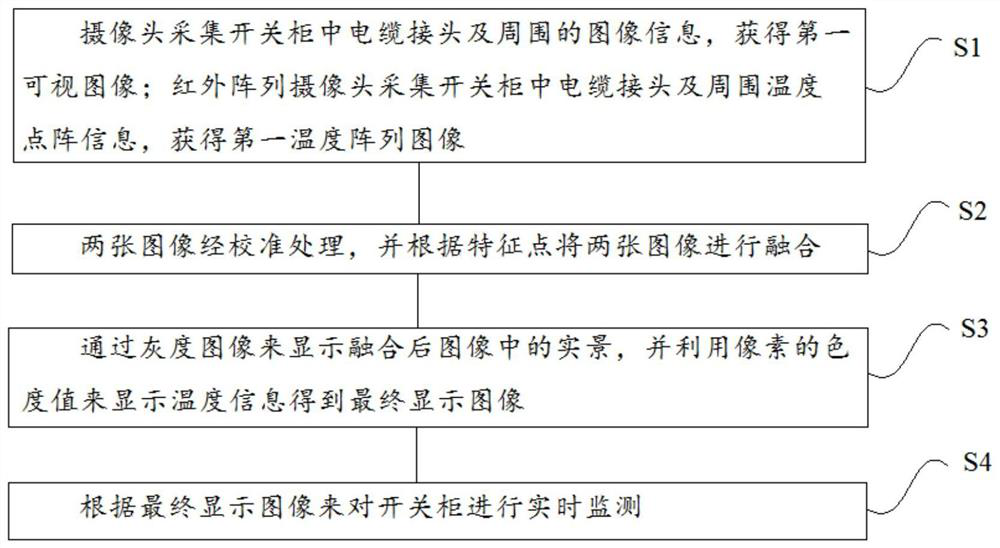
[0046] The basic idea of the embodiment of the present invention is that the camera collects the image information of the cable joint and its surroundings in the switch cabinet to obtain the first visible image; the infrared array camera collects the temperature lattice information of the cable joint and its surroundings in the switch cabinet to obtain the first temperature array image ; The two images are calibrated, and the two images are fused according to the feature points; the real scene in the fused image is displayed through the grayscale image, and the temperature information is displayed by the chromaticity value of the pixel to obtain the final display image; according to the final Display images for real-time monitoring of switchgear. The final display image can know the situation of the cable joint and the surrounding temperature gradient, which provides a reliable basis for the fault diagnosis of the switchgear.
[0047] Based on the above ideas, the embodiment...
Embodiment 2
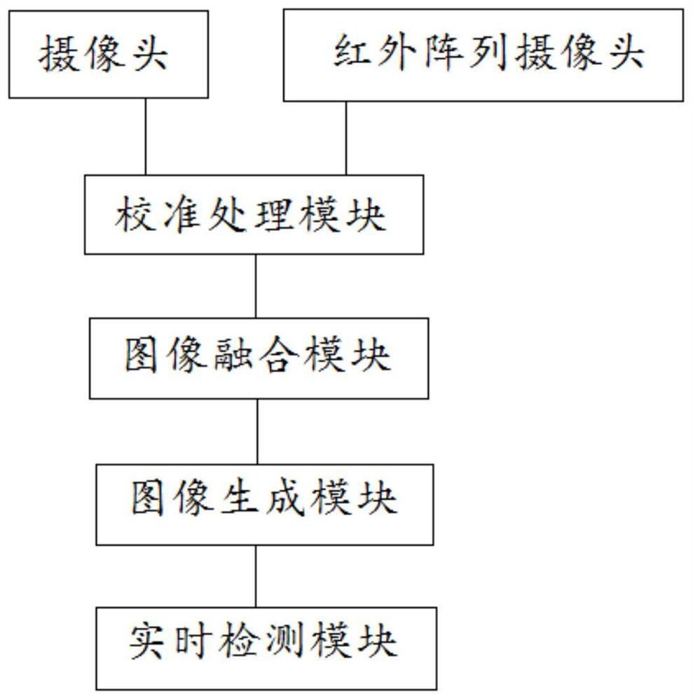
[0064] figure 2 It is a structural schematic diagram of a switch cabinet real-time monitoring system based on the cable joint and its surrounding temperature provided in the second embodiment of the present invention. The switchgear real-time monitoring system provided by the embodiment of the present invention can implement the switchgear real-time monitoring method based on the cable joint and its surrounding temperature provided by the first embodiment of the present invention, and has corresponding functional modules and beneficial effects for executing the method.
[0065] Real-time monitoring system of switchgear based on cable joint and its surrounding temperature, such as figure 2 As shown, it includes: a camera, used to collect the image information of the cable joint and its surroundings in the switch cabinet, to obtain the first visible image; an infrared array camera, used to collect the dot matrix information of the cable joint and the surrounding temperature in...
PUM
 Abstract
Description
Claims
Application Information