Wavelength conversion device

A wavelength conversion device and wavelength conversion technology, which are applied in lighting devices, projection devices, instruments, etc., can solve the problems of deterioration of the phosphor layer, sharp reduction and limitation of the light output rate of the reflective wavelength conversion device, etc.

Inactive Publication Date: 2021-03-30
DELTA ELECTRONICS INC
View PDF2 Cites 0 Cited by
  • Summary
  • Abstract
  • Description
  • Claims
  • Application Information

AI Technical Summary

Problems solved by technology

However, the existing reflective wavelength conversion device only dissipates heat by adding a heat sink on the other side of the substrate relative to the reflective layer, and its effective heat dissipation area is limited. Under the condition of high-power excitation light, it cannot dissipate the fluorescent layer in time when it is excited by the excitation light source. The heat generated causes the fluorescent layer to continue to operate at high temperature and degrades, which in turn causes the light output rate of the reflective wavelength conversion device to drop sharply
In addition, the structure of the transmissive wavelength conversion device includes a light-transmitting substrate and a fluorescent layer. Due to the high thermal resistance between the fluorescent layer and the light-transmitting substrate, it is also unable to dissipate the fluorescence in time under the condition of high-power excitation light. The heat generated when the layer is excited by the excitation light source will easily make the fluorescent layer continue to operate at high temperature and deteriorate

Method used


Image

  • Wavelength conversion device
  • Wavelength conversion device
  • Wavelength conversion device

Examples


Embodiment Construction

[0046] Some typical embodiments embodying the features and advantages of the present invention will be described in detail in the description in the following paragraphs. It should be understood that the present invention can have various changes in different forms without departing from the protection scope of the present invention, and the description and drawings therein are only used for illustration in nature, not for limitation this invention.

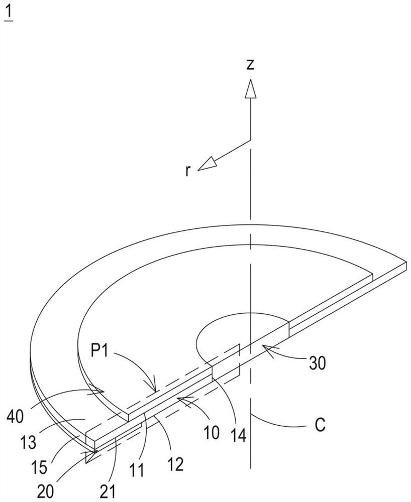
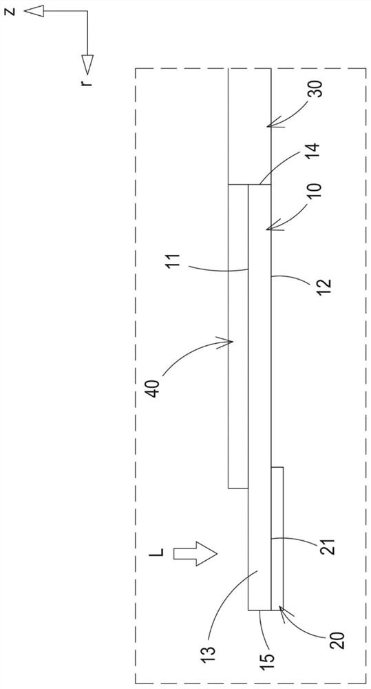
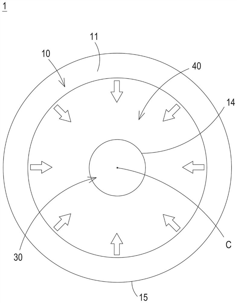
[0047] figure 1 is a cross-sectional structure diagram of the wavelength conversion device according to the first embodiment of the present invention. figure 2 yes figure 1 Cross-sectional view of the P1 region in . image 3 is a top view of the wavelength conversion device in the first embodiment of the present invention. In this embodiment, the wavelength conversion device 1 can be, for example but not limited to, a color wheel applied to a projector. The wavelength conversion device 1 includes a wavelength conversion plate...


PUM

PropertyMeasurementUnit
thicknessaaaaaaaaaa
thicknessaaaaaaaaaa
thicknessaaaaaaaaaa

Abstract

A wavelength conversion device comprises a wavelength conversion plate, a reflecting layer, a driving element and a heat conduction layer. The wavelength conversion plate is provided with an inner side edge, at least one surface and at least one conversion area. The reflecting layer is arranged on at least one surface of the wavelength conversion plate. The driving element is arranged on the innerside edge of the wavelength conversion plate and used for moving the wavelength conversion plate. The heat conduction layer is arranged on at least one surface of the wavelength conversion plate, connected to the at least one conversion area and used for conducting heat generated by the at least one conversion area during wavelength conversion. By arranging the heat conduction layer on at least one surface of the wavelength conversion plate, the heat conduction layer can be directly connected to the conversion region, so that heat generated by the conversion region during wavelength conversion can be effectively dissipated. Meanwhile, reduction of wavelength conversion efficiency due to accumulation of heat in a conversion region caused by obstruction of a heat dissipation path by high heat resistance of the reflecting layer can be avoided.

Description

technical field [0001] The invention relates to a wavelength conversion device, in particular to a wavelength conversion device for improving heat conduction efficiency. Background technique [0002] The wavelength conversion device uses, for example, a laser light source to excite phosphors to obtain predetermined monochromatic light or polychromatic light, and has been widely used in lighting sources, projection displays and other fields. Taking the projection display as an example, the required display color can be produced by using the laser light source to be incident on the phosphor color wheel. [0003] In projection display applications, wavelength conversion devices can be classified into reflective and transmissive devices. Taking the reflective wavelength conversion device as an example, its structure mainly includes a substrate, a reflective layer, and a fluorescent layer. The reflective layer is arranged between the substrate and the fluorescent layer. After th...

Claims


Application Information

Patent Timeline
Patent Type & Authority Applications(China)
IPC IPC(8): G02B26/00G03B21/14G03B21/16
CPCG02B26/008G03B21/14G03B21/16C09K11/7774H01L33/505H01L33/60H01L33/507H01L33/644G03B21/2066G03B21/204C09K11/02F21K9/64
Inventor 李日琪杨立诚
Owner DELTA ELECTRONICS INC
Why Eureka
Try Eureka