Electronic control unit and electric power steering with electronic control unit

A technology of electronic control unit and electrical connection, which is applied in the direction of electric steering mechanism, circuit heating device, electrical components, etc., and can solve problems such as not considering heat dissipation

Inactive Publication Date: 2018-09-07
DENSO CORP
View PDF6 Cites 0 Cited by
  • Summary
  • Abstract
  • Description
  • Claims
  • Application Information

AI Technical Summary

Problems solved by technology

[0003] However, JP-A-2011-23459 does not consider dissipating the heat generated in the semiconductor module to the same side as the board

Method used


Image

  • Electronic control unit and electric power steering with electronic control unit
  • Electronic control unit and electric power steering with electronic control unit
  • Electronic control unit and electric power steering with electronic control unit

Examples


no. 1 approach

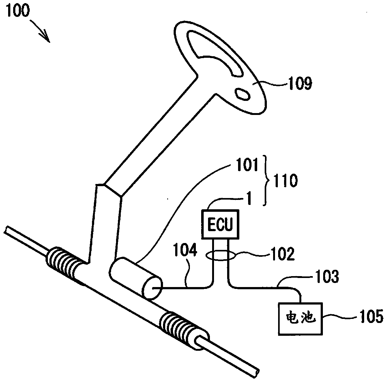
[0039] Such as figure 1 As shown in , the electronic control unit 1 according to the first embodiment of the present disclosure is used in an electric power steering device 110 of a vehicle. The electronic control unit 1 drives and controls the electric motor 101 as a rotating electric machine based on the steering torque signal and the vehicle speed signal so that the electric motor 101 can generate assist torque that helps the driver to steer the vehicle. The electric power steering device 110 includes an electronic control unit 1 and a motor 101 .

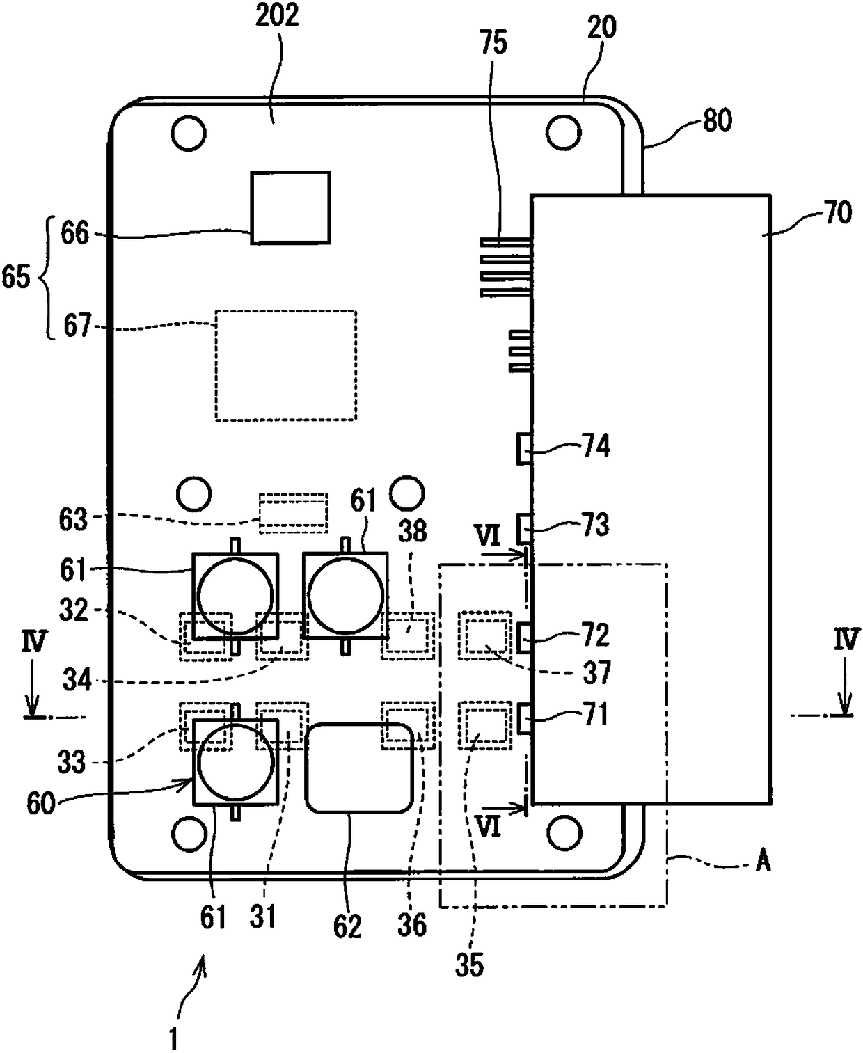
[0040] Such as image 3 and Figure 4 As shown, the electronic control unit 1 includes a board 20 , heat generating devices 31 to 38 , a connector 70 and a heat sink 80 .

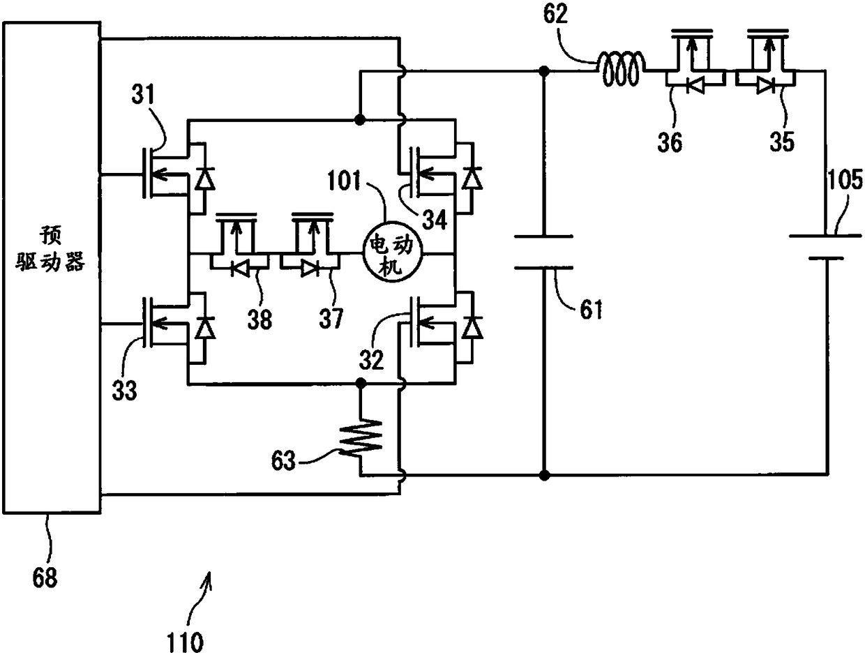
[0041] The heat generating devices 31 to 38 are field effect transistors, such as metal oxide semiconductor field effect transistors (MOSFETs). According to the first embodiment, the heat generating devices 31 to 34 are driving devices for driving purpose...

no. 2 approach

[0105] Refer below Figure 9 and Figure 10 An electronic control unit 2 according to a second embodiment of the present disclosure will be described. Figure 9 corresponds to Figure 4 ,and Figure 10 corresponds to Figure 5 . The second embodiment is similar to the first embodiment but differs as follows.

[0106] The electronic control unit 2 includes a radiator 86 instead of the radiator 80 . The pillar portion 87 of the heat sink 86 is different in shape from the pillar portion 83 of the heat sink 80 .

[0107] The pillar portion 87 protrudes from the base portion 81 toward the plate 20 . For example, the pillar portions 87 are arranged in a grid manner. Tips of the pillar portions 87 are separated from the first surface 201 of the board 20 . That is, there is a space between the tip of the pillar portion 87 and the first surface 201 of the board 20 . Therefore, unlike in the first embodiment, no green mask is formed at a position facing the pillar portion 87 o...

no. 3 approach

[0110] Refer below Figure 11 and Figure 12 An electronic control unit 3 according to a third embodiment of the present disclosure will be described. Figure 11 corresponds to Figure 4 ,and Figure 12 corresponds to Figure 5 . The third embodiment is similar to the first embodiment but differs as follows.

[0111] The electronic control unit 3 includes a radiator 88 instead of the radiator 80 . Unlike the heat sink 80, the heat sink 88 does not have a pillar part. Therefore, the heat sink 88 has a flat portion 89 at a position facing the MOSFETs 31 to 38 . The heat dissipation gel 84 is placed between the flat portion 89 and the MOSFETs 31 to 38 .

[0112] In the above structure, although the heat generated in the MOSFETs 31 to 38 is not dissipated from the sides of the MOSFETs 31 to 38 to the heat sink 88, the heat can be dissipated from the back of the MOSFETs 31 to 38 in the same manner as in the first embodiment. to radiator 88. In addition, since the heat sin...


PUM


Abstract

An electronic control unit and an electric power steering apparatus having the electronic control unit are provided. The electronic control unit includes boards (20, 120, 130, 140), heat generating devices (31-38, 41-48, 51-58), connectors (70) and heat sinks (80, 86, 88). The board has an insulating layer (26) and wiring patterns (21, 141) partially exposed outside the insulating layer. A heat generating device is mounted on the board and electrically connected to the wiring pattern. A connector (70) is positioned adjacent to the heat generating device and has connection terminals (71, 73) connected to the wiring pattern. A heat sink is positioned opposite the board across the heat generating device, and the heat sink is in contact with the heat generating device to dissipate heat from the heat generating device. The wiring pattern has a land pattern (211, 214, 218) including a mounting portion (212, 219) and a connection portion (711). The heat generating device is mounted on the mounting portion. The connection terminal of the connector is connected to the connection part.

Description

technical field [0001] The present disclosure relates to an electronic control unit and an electric power steering device having the same. Background technique [0002] Electronic control units that dissipate heat generated from a semiconductor module to another object such as a heat sink are known. For example, in JP-A-2011-23459 corresponding to US2011 / 0013370A1, an electrically insulating heat sink and heat dissipation gel are placed between the semiconductor module and the heat sink, and the heat generated in the semiconductor module is dissipated from the back to the heat sink. [0003] However, JP-A-2011-23459 does not consider dissipating the heat generated in the semiconductor module to the same side as the board. Contents of the invention [0004] In view of the above circumstances, an object of the present disclosure is to provide an electronic control unit in which heat generated in a heat generating device is efficiently dissipated, and an object of the prese...

Claims


Application Information

Patent Timeline
Patent Type & Authority Patents(China)
IPC IPC(8): H01L23/498H01L23/367B62D5/04
CPCH05K3/3415H05K2201/10189H05K2201/066H05K1/0209Y02P70/50H05K7/209H05K7/1432
Inventor 西本良大多信介
Owner DENSO CORP
Why Eureka
Try Eureka