
Device for carrying out timing recovery error detection in digital receiver and application method

An error detection and timing recovery technology, applied in the field of communications, can solve problems such as poor instantaneous phase tracking performance, inability of equalizers to track channel and noise changes, and sampling phase sensitivity.

Active Publication Date: 2021-03-30
MIANYANG NETOP TELECOM EQUIP
View PDF4 Cites 0 Cited by
  • Summary
  • Abstract
  • Description
  • Claims
  • Application Information

AI Technical Summary

Problems solved by technology

[0006] 1. After the adaptive equalizer converges, the update of the equalizer will be stopped, and only the timing recovery module will be left to work. However, in this mode, the equalizer cannot track the changes of the channel and noise, resulting in a decline in performance after long-term operation [1 ]
[0007] 2. Improve the convergence speed of timing recovery to make it much faster than the equilibrium convergence speed, but this can only significantly reduce the phase drift phenomenon, which cannot completely solve the phenomenon, and also reduces the jitter performance of timing recovery[2]
[0009] Although method 3 can solve the above two problems, its receiver uses a symbol rate equalizer. A major disadvantage of the symbol rate equalizer is that the equalization performance is very sensitive to the sampling phase. When the sampling phase is far from the optimal sampling position When , the performance of the receiver will drop significantly [3]
[0010] 4. Using an algorithm based only on equalizer taps, using the offset of the center of gravity of the equalizer taps or the relationship between partial taps of the equalizer to extract the timing error, but this type of algorithm has poor performance in instantaneous tracking of the phase and is relatively hysteresis. The sampling phase will be dispersed over a large range

Method used


Image

  • Device for carrying out timing recovery error detection in digital receiver and application method
  • Device for carrying out timing recovery error detection in digital receiver and application method
  • Device for carrying out timing recovery error detection in digital receiver and application method

Examples


Embodiment Construction

[0056] The present invention will be further described in detail below in conjunction with the accompanying drawings, so that those skilled in the art can implement it with reference to the description.

[0057] It should be understood that terms such as "having", "comprising" and "including" as used herein do not entail the presence or addition of one or more other elements or combinations thereof.

[0058] It should be noted that in the description of the present invention, the orientation or positional relationship indicated by the term is based on the orientation or positional relationship shown in the drawings, which is only for the convenience of describing the present invention and simplifying the description, and does not indicate or imply No device or element must have a specific orientation, be constructed, and operate in a specific orientation and therefore should not be construed as limiting the invention. In addition, the terms "first" and "second" are used for de...


PUM


Abstract

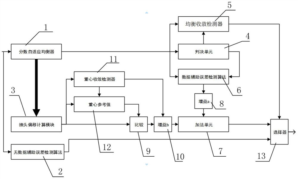
The invention discloses a device for carrying out timing recovery error detection in a digital receiver and an application method of the device. The device comprises a fraction adaptive equalizer anda no-data auxiliary error detection module which are respectively connected with a distortion receiving signal end, a tap offset calculation module and a judgment module which are connected with the fractional adaptive equalizer; an equalization convergence detector and a data auxiliary error detection module which are connected with the judgment module; a tap offset calculation module and a dataauxiliary error detection modulewhich are connected with the addition module; and an addition module, a no-data auxiliary error detection module and an equalization convergence detector which are allconnected with a selector for outputting a timing error signal. The invention provides a device for carrying out timing recovery error detection in a digital receiver and an application method of thedevice, and solves the problem of phase drift when adaptive equalization and timing recovery work together.

Description

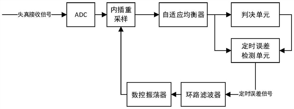
technical field [0001] The invention relates to a communication field. More specifically, the present invention relates to an apparatus for timing recovery error detection in a digital receiver and its application method. Background technique [0002] figure 2 It is a typical DSL transmission system. In this system, the central office generates the data master clock of the entire system, and the user end restores and reconstructs the data of the master clock through the received signal, and uses this clock as the sending clock (slave clock) of the user end, and the clock at the receiving end of the central office can be No adjustments or only phase adjustments are made, so the data clocks of the entire system are perfectly synchronized. [0003] In order to achieve the above purpose, the user end can use the all-digital timing recovery technology, such as image 3 As shown, the received signal is collected by a fixed sampling clock, and the error between the current samp...

Claims


Application Information

Patent Timeline
Patent Type & Authority Applications(China)
IPC IPC(8): H04B1/16H04L25/03
CPCH04B1/16H04L25/03885
Inventor 沈秋旭陈昌军肖东海刘燕兵张永明
Owner MIANYANG NETOP TELECOM EQUIP
Learn More