Glue blocking bracket

A bracket and glue blocking technology, which is applied in the direction of coating and liquid coating device on the surface, etc., can solve the problem of sticking to the outer surface of the bracket body and the colloid is easy to overflow, etc., so as to reduce capital investment and increase shift output , Improve the effect of assembly accuracy

Active Publication Date: 2021-04-02
FUJIAN FUYAO AUTOMOTIVE ALUMINIUM SYST CO LTD
View PDF6 Cites 0 Cited by
  • Summary
  • Abstract
  • Description
  • Claims
  • Application Information

AI Technical Summary

Problems solved by technology

[0005] The technical problem to be solved by the present invention is to provide a rubber retaining bracket, which solves the defects in the prior art that the colloid is easy to overflow and stick to the outer surface of the bracket body

Method used


Image

  • Glue blocking bracket
  • Glue blocking bracket
  • Glue blocking bracket

Examples


Embodiment 1

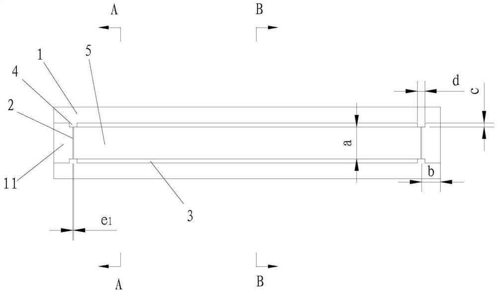
[0070] Please refer to Figure 1-Figure 5 and Figure 14-Figure 15 , a rubber blocking bracket, including a bracket body 1, a plurality of first rubber blocking parts 2, a plurality of second rubber blocking parts 3 and a plurality of supporting parts 4;

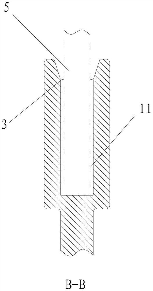
[0071] The top of the bracket body 1 is provided with an installation groove 11 for holding the colloid to bond the glass 5;

[0072] The inner walls on both sides of the installation groove 11 are respectively equipped with a plurality of supporting parts 4;

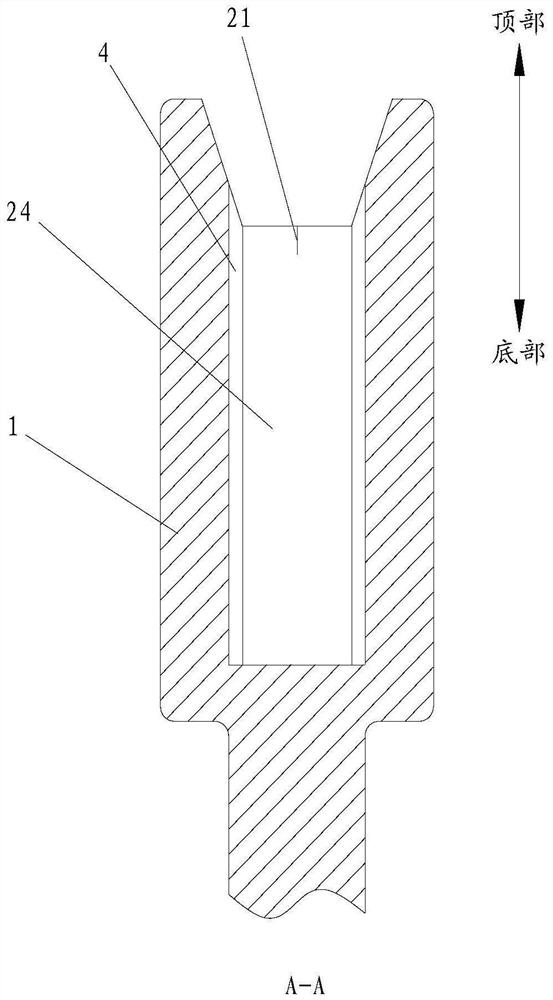
[0073] A plurality of first rubber stoppers 2 are correspondingly installed between two opposite supporting parts 4, and one end of the first rubber stoppers 2 is provided with a cutout 21 for installing glass 5;

[0074] A plurality of second rubber blocking members 3 are arranged oppositely on two oppositely arranged side walls of the installation groove 11 .

[0075] Preferably, there are two first rubber stoppers 2 and second rubber stoppers 3, and four support...

Embodiment 2

[0091] The difference between this embodiment and the first embodiment is that the second structure of the first rubber stop is defined.

[0092] refer to Figure 6-Figure 11 The two oppositely arranged side walls of the bracket body 1 are respectively provided with an assembly groove 12 that is isosceles trapezoidal when viewed from above;

[0093] refer to Figure 9 A V-shaped groove 22 is opened on the side of the first rubber blocking member 2 away from the second rubber blocking member 3 ; the notch 21 is opened in the V-shaped groove 22 .

[0094] refer to Figure 6-Figure 9 , the first glue stopper 2 includes a glued film 23 and two pieces of glued film 24; , and the other end is pressed against the second rubber blocking member 3; There is always a gap between the adhesive film 23 and the second rubber blocking member 3, so that the PU glue overflows evenly from the gap between the adhesive film 23 and the bracket body 1, and forms a strip-shaped adhesive strip 6 e...

Embodiment 3

[0105] The difference between this embodiment and the second embodiment is that the third structure of the first rubber stop is defined.

[0106] refer to Figure 12-Figure 15 The two oppositely arranged side walls of the bracket body 1 are respectively provided with an assembly groove 12 that is isosceles trapezoidal when viewed from above;

[0107] refer to Figure 12 and Figure 13 , the first rubber blocking member 2 includes a rubber blocking film 24 .

[0108] refer to Figure 12 and Figure 13 , the first rubber blocking member 2 is planar and vertically arranged between the two supporting parts 4 .

[0109] refer to Figure 12 and Figure 13 , the first rubber blocking member 2 is also provided with a saw-toothed notch 25 ;

[0110] Optionally, the height L of the notch 25 3 2mm~10mm, width W 3 2mm to 5mm.

[0111] The rubber blocking film 24 with serrated notches can also be manufactured by injection molding or extrusion plus rolling notches, and then assem...


PUM


Abstract

The invention discloses a glue blocking bracket which comprises a bracket body, multiple first glue blocking pieces, multiple second glue blocking pieces and multiple supporting parts. The top of thebracket body is provided with a mounting groove used for containing glue so as to be bonded with glass. The multiple supporting parts are arranged on the inner walls of the two sides of the mounting groove correspondingly. Each of the multiple first glue blocking pieces is correspondingly arranged between the two corresponding oppositely-arranged supporting parts, and a cutting opening used for mounting glass is formed in one end of each first glue blocking piece. The multiple second glue blocking pieces are oppositely arranged on the two oppositely-arranged side walls in the mounting groove.The defects that in the prior art, glue is prone to overflowing, and glue on the surface of a mold or glue on the de-gluing surface still needs to be cleaned away after bonding are overcome, and meanwhile the bonding efficiency is greatly improved.

Description

technical field [0001] The invention relates to the field of glazing technology, in particular to a rubber retaining bracket. Background technique [0002] At present, most of the bracket body is injected into the card slot through PU glue. After the glass is assembled into the card slot, the PU glue gradually fills the gap between the card slot and the glass, and forms a bonding relationship after curing. In the prior art, the following glue injection methods are usually used: direct glue injection, glue injection after setting a rubber stop in the bracket body, injection in the mold, and glue injection after setting a rubber stop strip in the mold. [0003] Among them, (1) the way of direct glue injection will overflow glue from the three sides of the bracket body card slot, which is not only troublesome to clean up, time-consuming and laborious, but also wastes glue; (2) taking the patent application number US20180202209A1 as an example, Install the rubber stopper in the...

Claims


Application Information

Patent Timeline
Patent Type & Authority Applications(China)
IPC IPC(8): B05C13/02B05C11/10
CPCB05C13/02B05C11/10
Inventor 沙瑞斌俞裕生许主竹王鹏
Owner FUJIAN FUYAO AUTOMOTIVE ALUMINIUM SYST CO LTD
Why Eureka
Try Eureka