
Rocker arm type vibrating trough

A vibrating tank and rocker arm type technology, applied in the direction of vibration suppression adjustment, filter screen, grille, etc., can solve the problems of low operating cost, pollute the environment, and few separation categories, and achieve the protection of the vibration tank, damping vibration, and inertia. force effect

Active Publication Date: 2021-04-02
德清鸿捷铸机有限公司
View PDF6 Cites 2 Cited by
  • Summary
  • Abstract
  • Description
  • Claims
  • Application Information

AI Technical Summary

Problems solved by technology

[0003] The existing vibrating tank operating system is too complicated, and the existing vibrating drive equipment and control systems are too many, resulting in high operating costs, and there are few separation categories in the vibratory screening of materials, and the dust particles generated by the separation Floating in the air, polluting the environment

Method used


Image

  • Rocker arm type vibrating trough
  • Rocker arm type vibrating trough
  • Rocker arm type vibrating trough

Examples


Embodiment Construction

[0027] The following will clearly and completely describe the technical solutions in the embodiments of the present invention with reference to the accompanying drawings in the embodiments of the present invention. Obviously, the described embodiments are only some, not all, embodiments of the present invention.

[0028] In describing the present invention, it should be understood that the terms "upper", "lower", "front", "rear", "left", "right", "top", "bottom", "inner", " The orientation or positional relationship indicated by "outside", etc. is based on the orientation or positional relationship shown in the drawings, and is only for the convenience of describing the present invention and simplifying the description, rather than indicating or implying that the referred device or element must have a specific orientation, so as to Specific orientation configurations and operations, therefore, are not to be construed as limitations on the invention.

[0029] refer to Figure ...


PUM


Abstract

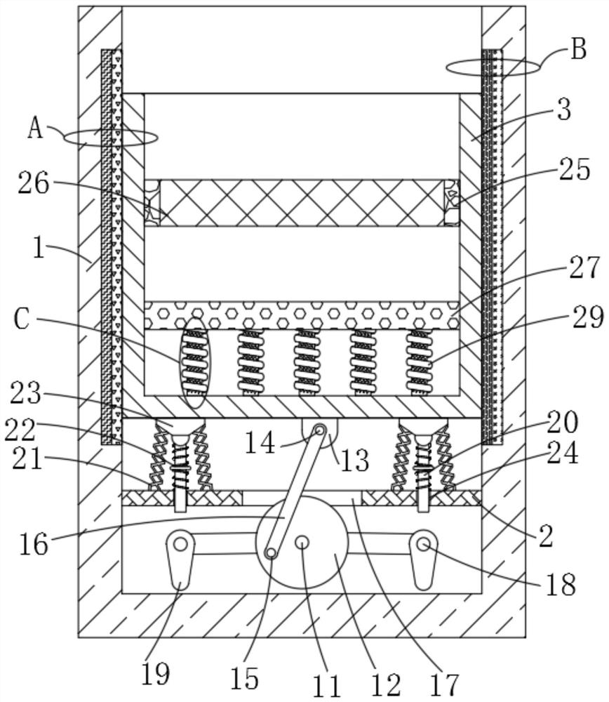
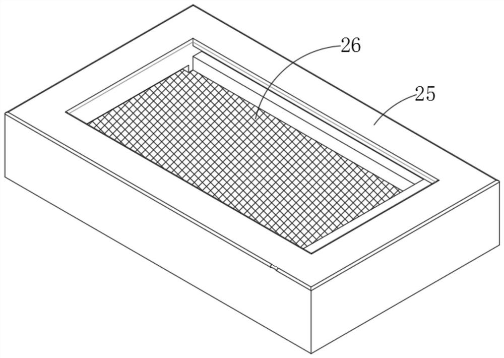
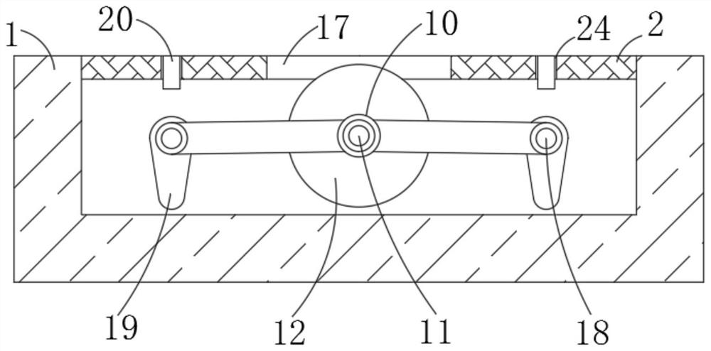
The invention discloses a rocker arm type vibrating trough comprising a machine barrel, and a bearing plate is fixedly installed in the machine barrel; a vibrating trough body is arranged above the bearing plate, and slidably connected with the inner walls of the two sides of the machine barrel; and a first adsorption assembly is arranged in the inner wall of the left side of the machine barrel, and a second adsorption assembly is arranged in the inner wall of the right side of the machine barrel. According to the rocker arm type vibrating trough, through arrangement of a driving mechanism, asubdivision mechanism, the first adsorption assembly, the second adsorption assembly, a power assembly and an auxiliary reset assembly, one motor is used for driving a plurality of components to achieve rocker arm type reciprocating vibration of the vibration groove, and the problems that an existing vibrating through operation system is too complex and high in operation cost are solved; multi-layer material screening treatment can be completed through twisting of triangular crushing pieces on springs, dust particles generated through separation can be adsorbed and collected through positive charges and negative charges generated in the up-down vibration process; and environmental pollution is avoided.

Description

technical field [0001] The invention relates to the technical field of vibrating tank production and processing, in particular to a rocker-arm type vibrating tank. Background technique [0002] Vibrating tanks are used in underground stopes, roadways, tunnels and other engineering shipments, and can vibrate and screen transshipped materials. The existing vibrating tank system usually consists of a vibrating tank, a vibrator, a frame, a chassis, power and control system composition. [0003] The existing vibrating tank operating system is too complicated, and the existing vibrating drive equipment and control systems are too many, resulting in high operating costs, and there are few separation categories in the vibratory screening of materials, and the dust particles generated by the separation Floating in the air, polluting the environment. Contents of the invention [0004] The purpose of the present invention is to solve the shortcomings in the prior art, and propose a...

Claims


Application Information

Patent Timeline
Patent Type & Authority Applications(China)
IPC IPC(8): B07B1/34B07B1/42B07B1/46B03C3/28F16F15/067
CPCB03C3/28B07B1/343B07B1/42B07B1/46B07B2201/04F16F15/067
Inventor 陈红雷陈浩然陈锦文王权凯余文博
Owner 德清鸿捷铸机有限公司
Learn More