Preparation method of static end tooth for electric tool

A technology for electric tools and static ends, which is applied in the field of preparation of static end teeth for electric tools, can solve the problems of limited local density improvement, and achieve the effect of increasing hardness and embryo body density

Pending Publication Date: 2021-04-02
苏州中鼎冶金有限公司
View PDF0 Cites 0 Cited by
  • Summary
  • Abstract
  • Description
  • Claims
  • Application Information

AI Technical Summary

Problems solved by technology

However, warm pressing can only increase the overall density value, and has a limit

Method used


Image

  • Preparation method of static end tooth for electric tool

Examples


specific Embodiment 1

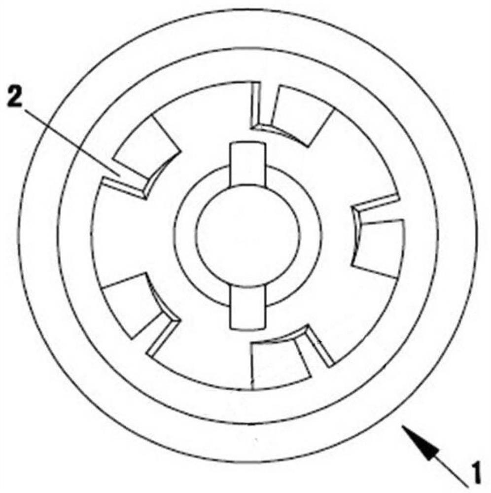
[0014] Specific embodiment one, please refer to figure 1 , a method for preparing static end teeth for electric tools, characterized in that the steps are:

[0015] (1) A plurality of bosses 2 are evenly distributed on the upper surface of the static end tooth body 1; top powder holes are respectively opened on the lower surface of the static end tooth body 1 corresponding to the plurality of bosses 2;

[0016] (2) There are five bosses 2, which are evenly distributed on the upper surface of the static end tooth body 1, and there are five top powder holes, which are respectively arranged on the static end tooth body corresponding to the bosses 2 on the lower surface of the

[0017] (3) On the lower surface of the static end tooth corresponding to the boss 2 on the upper surface, there are powder ejector holes respectively, and the powder ejector holes play the role of powder ejector when the static end teeth are pressed; during pressing, the powder ejector The metallurgical ...


PUM


Abstract

The invention discloses a preparation method of a static end tooth for an electric tool. The preparation method of the static end tooth for the electric tool can improve the local density of a productand improve the strength and hardness of the product. According to the method, the density of the product is improved in a powder ejection mode; the local density of the product can be improved by 0.25 per cubic centimeter, the torque of the product is greatly improved, and the percent of pass of the product is also improved.

Description

technical field [0001] The invention discloses a preparation method of static end teeth for electric tools. Background technique [0002] The common static end tooth structure in drill electric tools is as follows: figure 1 As shown, the static end tooth includes a static end tooth body 1 , and a plurality of bosses 2 are uniformly arranged on the upper surface of the static end tooth body 1 . Usually, there are certain hardness and wear resistance requirements for the boss on the static end tooth body. During use, often because the hardness of this boss place is not enough, and fracture occurs. Therefore, in the powder metallurgical design of the static end teeth, increasing the density of the boss part is the key point of the design scheme. [0003] In the powder metallurgy industry, increasing the density of parts is a main method to improve the hardness of products, especially the density of key parts, which is an important indicator to determine product performance. ...

Claims


Application Information

Patent Timeline
IPC IPC(8): B22F5/08B22F3/02
CPCB22F3/02B22F5/08
Inventor 樊晔朱腾达于化超李伟
Owner 苏州中鼎冶金有限公司
Why Eureka
Try Eureka