
Adjustable safe bush hammer

A chisel machine, adjustable technology, applied in the direction of work accessories, stone processing tools, stone processing equipment, etc., can solve the safety hazards of workers and other problems, achieve the effect of improving practicability, preventing tampering, and improving safety factor

Pending Publication Date: 2021-04-02
深圳市河图建设项目管理有限公司
View PDF1 Cites 0 Cited by
  • Summary
  • Abstract
  • Description
  • Claims
  • Application Information

AI Technical Summary

Problems solved by technology

[0004] Based on the technical problem that the flying stones may cause safety hazards to the staff when the existing chisel is working, the present invention proposes an adjustable safety chisel

Method used


Image

  • Adjustable safe bush hammer
  • Adjustable safe bush hammer
  • Adjustable safe bush hammer

Examples


Embodiment 1

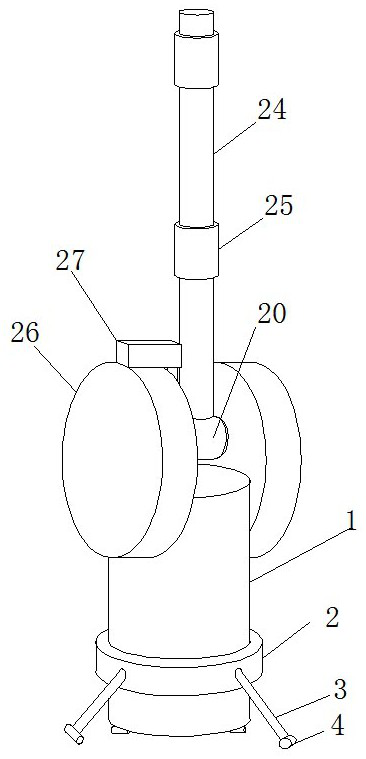
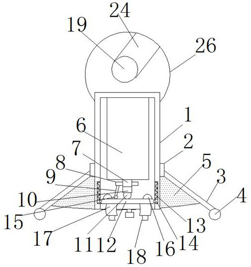
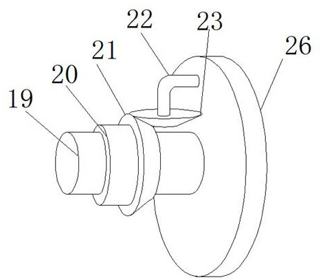
[0029] refer to Figure 1-5 , an adjustable safety chisel machine, including a power chamber 1, an air motor 6 is welded on the top inner wall of the power chamber 1, and a rotating shaft 7 is welded on the output end of the air motor 6, and a rotating shaft is welded on the outer ring of the rotating shaft 7. The connecting rod 9 is welded on one side of the bottom end of the piece 8 and the rotating piece 8, and the sliding ball 15 is welded on one end of the connecting rod 9. A rectangular groove is opened on both sides of the bottom end of the power chamber 1, and the power chamber 1 is inside the rectangular groove. A first spring 13 is provided, the bottom end of the first spring 13 is welded with a moving block 14, and one end of the moving block 14 is connected with a deflector 12 through a rotating shaft, and a semicircular protrusion 16 is welded on both sides of the top of the deflecting plate 12, and the rotating shaft The inner ring of 7 is welded with a connectio...

Embodiment 2

[0038] refer to Figure 6 , an adjustable safety chisel machine. Compared with Embodiment 1, in this embodiment, in order to improve the ability of the chisel head to chisel the wall, a cavity is opened inside the fixed column 17, and the fixed column 17 is located in the cavity. The inner wall of the top end is welded with a threaded rod 33, the threaded rod 33 is provided with a threaded bearing 34, the inner ring of the threaded bearing 34 is welded with a chisel head 18, and the chisel head 18 is slidably connected with the fixed column 17 at the cavity, When the air motor 6 drives the deflection plate 12 to deflect, the chisel head 18 begins to chisel the wall, and simultaneously due to the influence of the reaction force, the chisel head 18 drives the threaded bearing 34 to rotate on the threaded rod 33, and the threaded bearing 34 rotates upwards to When unable to rotate, the sliding ball 15 still has a pressing force on the semicircular protrusion 16, so that the chise...


PUM


Abstract

The invention belongs to the technical field of construction equipment, and particularly relates to an adjustable safe bush hammer. To solve the technical problem that splashing stones may cause safety hazards to workers when an existing bush hammer works, the following scheme is provided at present, a power chamber is included, and a pneumatic motor is fixedly connected to the inner wall of the top end of the power chamber; and a rotating shaft is fixedly connected to the output end of the pneumatic motor, a rotating piece is fixedly connected to the outer ring of the rotating shaft, a connecting rod is fixedly connected to one side of the bottom end of the rotating piece, a sliding ball is fixedly connected to one end of the connecting rod, rectangular grooves are formed in the two sidesof the bottom end of the power chamber, first springs are arranged in the rectangular grooves of the power chamber, and the bottom ends of the first springs are fixedly connected with moving blocks.According to the adjustable safe bush hammer, a threaded bearing and the sliding ball are arranged, the pneumatic motor is started to drive the sliding ball and a semi-circular ball to extrude each other, two chisel heads are driven to periodically chisel a wall surface, meanwhile, elastic cloth intercepts some splashed stones, and the safety performance is improved.

Description

technical field [0001] The invention relates to the technical field of designing construction equipment, in particular to an adjustable safety chisel. Background technique [0002] In our daily life, most of the existing chisel machines have multiple chisel heads. When these chisel machines are working, because the multiple chisel heads press the wall together, large stone flakes may be produced. Fly to the staff under the impact force, causing danger to the personal safety of the staff. [0003] After retrieval, the Chinese patent application number is CN201821597263.5, which discloses a chisel machine for building construction, including a handrail rod, a load plate, a chisel box, a bracket, and a traction rope. A bracket is provided on one side of the load plate, and the bracket One side is connected to the handrail rod, and the bottom end of the other side of the bracket is provided with a chisel box; the bearing plate includes a board body, a servo motor, a fan, and an...

Claims


Application Information

Patent Timeline
Patent Type & Authority Applications(China)
IPC IPC(8): B28D1/26B28D7/00B28D7/02
CPCB28D1/265B28D7/00B28D7/02
Inventor 李超柳晓云柳泽滨张世杰陈俊君刘钦杰
Owner 深圳市河图建设项目管理有限公司
Learn More