Automatic cutting device used for porous extrusion molding equipment and using method of automatic cutting device

An automatic cutting device, cutting device technology, applied in the direction of metal processing, etc., can solve the problems of increasing the labor intensity of operators, affecting production efficiency, material waste, etc., and achieve the effect of simple structure, high work efficiency and reducing waste

Pending Publication Date: 2021-04-02
NINGBO JINFENG WELDING & CUTTING MACHINERY MFR
View PDF6 Cites 2 Cited by
  • Summary
  • Abstract
  • Description
  • Claims
  • Application Information

AI Technical Summary

Problems solved by technology

In order to make the produced profiles meet the length requirements, when cutting, the batch can only be cut after the shortest profile in the same batch meets the length requirements, and then other profiles that exceed the length are shortened to meet the length requirements; this has resulted in a serious waste of materials, an increase in cost, and an additional process, which affects production efficiency and increases the labor intensity of operators

Method used


Image

  • Automatic cutting device used for porous extrusion molding equipment and using method of automatic cutting device
  • Automatic cutting device used for porous extrusion molding equipment and using method of automatic cutting device
  • Automatic cutting device used for porous extrusion molding equipment and using method of automatic cutting device

Examples


Embodiment Construction

[0026] In order to understand the technical scheme of the present invention more intuitively and completely, the non-limiting feature descriptions are as follows in conjunction with the accompanying drawings of the present invention:

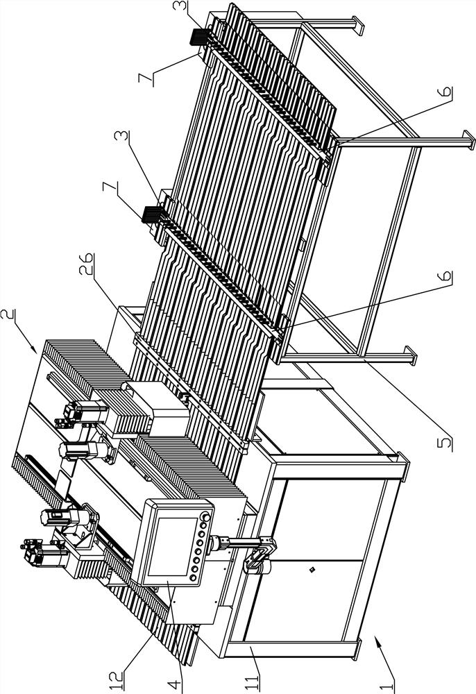
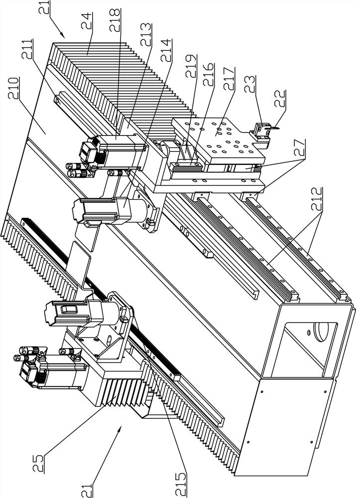
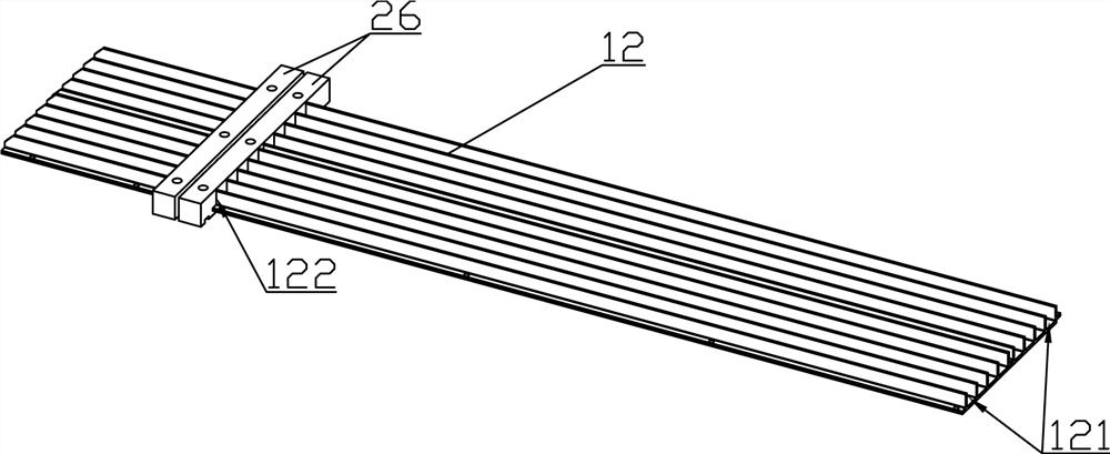
[0027] Such as Figure 1 to Figure 3 As shown, an automatic cutting device for porous extrusion equipment includes a diversion guide device 1 and a cutting device 2. The diversion guide device 1 includes a base 11 and a diversion guide plate 12 arranged on the base 11. On the diversion guide plate 12 There are several guide passages 121, and the splitter guide plate 12 is provided with opening grooves 122 communicating with each guide passage 121. One end of several guide passages 121 is arranged in one-to-one correspondence with the discharge holes of the extrusion molding equipment, and the other ends of several guide passages 121 One end is provided with a fixed-length detection mechanism 3 in one-to-one correspondence, and the fixed-length d...


PUM


Abstract

The invention discloses an automatic cutting device used for porous extrusion molding equipment and a using method of the automatic cutting device. The automatic cutting device comprises a flow dividing guide device and a cutting device. The flow dividing guide device comprises a base and a flow dividing guide plate, multiple guide channels are formed in the flow dividing guide plate, and an opengroove communicating with all the guide channels is formed in the flow dividing guide plate. One ends of the multiple guide channels are arranged in one-to-one correspondence to discharge holes of theextrusion molding equipment, the other ends of the multiple guide channels are provided with fixed-length detection mechanisms in one-to-one correspondence, and the fixed-length detection mechanismsare used for detecting the positions of the profiles in the guide channels and sending signals. The cutting device comprises a driving mechanism, the driving mechanism is electrically connected with each fixed-length detection mechanism, the output end of the driving mechanism is provided with a cut-off tool corresponding to the open groove, and the driving mechanism is used for receiving signalsand driving the cut-off tool to cut off the profiles according to the signals. The automatic cutting device has the advantages of being high in work preparing efficiency and capable of reducing the labor intensity of operators and saving materials.

Description

technical field [0001] The invention relates to the technical field of extrusion equipment, in particular to an automatic cutting device for porous extrusion equipment and a usage method thereof. Background technique [0002] Extrusion equipment is an important plastic machinery, generally called extruder or extruder, mainly used to produce long strips or long rods and other profiles. The basic working principle is to input granular materials into the equipment, and through the pressure and shear force generated by the screw rotation, the materials can be fully plasticized and uniformly mixed, and at the same time, under the work of the heating device, the materials are formed into a molten state. And extrude from the discharge hole, by using different discharge holes, you can get profiles with different specifications or shapes. Generally, there is only one discharge hole, but the work efficiency of this structure is low, and it is difficult to meet mass industrial product...

Claims


Application Information

Patent Timeline
Patent Type & Authority Applications(China)
IPC IPC(8): B29C48/00B29C48/25B29C48/355B29C48/92B26D1/06
CPCB29C48/0022B29C48/25B29C48/355B29C48/92B26D1/06
Inventor 章德均刁海波
Owner NINGBO JINFENG WELDING & CUTTING MACHINERY MFR
Why Eureka
Try Eureka