Equivalent feeding and dumping device capable of adjusting conveying capacity
A conveying volume and feeding technology, which is applied in the field of volume feeding and dumping devices, can solve the problems of low efficiency and human harm, and achieve the effect of adjustable feeding volume and stable and efficient reciprocating feeding.
- Summary
- Abstract
- Description
- Claims
- Application Information
AI Technical Summary
Problems solved by technology
Method used
Image
Examples
Embodiment 1
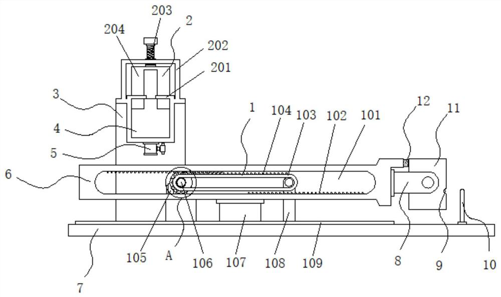
[0025] Example 1: See Figure 1-4 , an equal-volume feeding and dumping device capable of adjusting the conveying volume, comprising a fixed frame 3 and a bottom plate 7, one side of the top of the bottom plate 7 is fixedly connected with a fixed frame 3, and the top of the fixed frame 3 is inlaid with a reserved pool 4. The bottom of the retention pool 4 is fixedly connected with a valve pipe 5, the top of the fixed frame 3 is provided with an adjustment structure 2, the top of the bottom plate 7 is provided with a driving mechanism 1, and one side of the top of the bottom plate 7 is provided with a dumping structure;
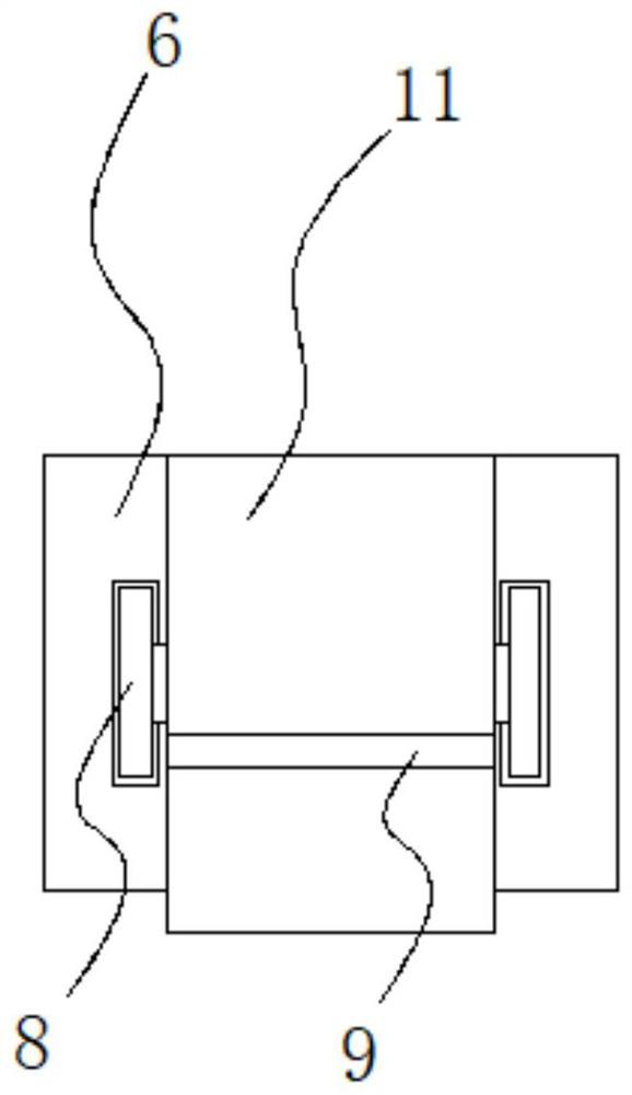
[0026] see Figure 1-4 , a kind of equal-feeding and dumping device capable of adjusting the delivery volume also includes a dumping structure, the dumping structure includes a movable plate 6, the movable plate 6 is arranged on the top of the bottom plate 7, and the two ends of one side of the movable plate 6 are fixedly connected with a group Positioning pl...
Embodiment 2
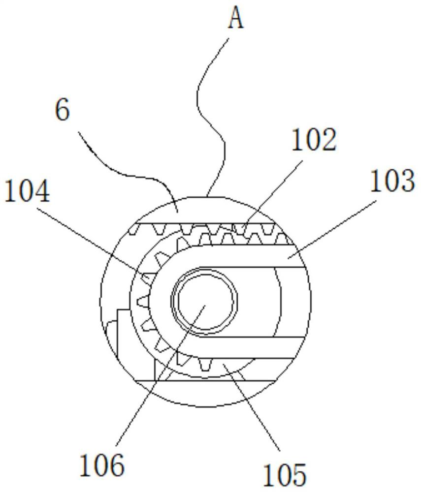
[0029] Embodiment 2: drive mechanism 1 is made up of empty groove 101, tooth bar 102, transmission belt 103, gear block 104, motor 105, rotating shaft 106, slide block 107, support 108 and chute 109, and empty groove 101 is arranged on the movable plate 6 Inside, one side of the top end and one side of the bottom end of the cavity 101 are respectively fixedly connected with a group of racks 102, and a motor 105 is fixedly connected to the top of the bottom plate 7. The model of the motor 105 is Y90S-4, and the output end of the motor 105 is fixed Connected with a rotating shaft 106, the outside of the rotating shaft 106 is movably connected with a transmission belt 103, one side of the transmission belt 103 is movably connected with a bracket 108, the bracket 108 is fixedly connected with the bottom plate 7, and the top of the transmission belt 103 is fixedly connected with a tooth block 104, the tooth block 104 It is movably connected with the rack 102, the slider 107 is fixed...
Embodiment 3
[0032] Embodiment 3: The adjustment structure 2 is composed of a limit groove 201, a positioning frame 202, a bolt 203 and a filling block 204. The positioning frame 202 is fixedly connected to the top of the fixed frame 3, and a set of limiters are respectively fixedly connected to both sides of the top of the fixed frame 3. Position slot 201, bolt 203 is movably connected to the top of positioning frame 202, bolt 203 runs through the top of positioning frame 202 and extends to the bottom of positioning frame 202, and is fixedly connected with filling block 204, and filling block 204 is movably connected with limiting groove 201;
[0033] The width inside the limiting groove 201 is greater than the width of the filling block 204, and the length of the filling block 204 is less than the length inside the spacer 202;
[0034] Specifically, such as figure 1 and Figure 4As shown, before feeding, the filling block 204 can be driven to move by turning the bolt 203. After the fill...
PUM
 Abstract
Description
Claims
Application Information
 - R&D
- Intellectual Property
- Life Sciences
- Materials
- Tech Scout
- Unparalleled Data Quality
- Higher Quality Content
- 60% Fewer Hallucinations
Browse by: Latest US Patents, China's latest patents, Technical Efficacy Thesaurus, Application Domain, Technology Topic, Popular Technical Reports.
© 2025 PatSnap. All rights reserved.Legal|Privacy policy|Modern Slavery Act Transparency Statement|Sitemap|About US| Contact US: help@patsnap.com


