
Differential gear

A technology of differential transmission and equipment, applied in the direction of transmission, mechanical equipment, hoisting device, etc., can solve the problems of inconvenient winding, stuck, unable to adjust the transmission ratio freely and quickly, and reduce switching stuck and, Improves service life and facilitates resetting

Active Publication Date: 2022-08-09
NANJING YUSHENG ROBOT CO LTD
View PDF6 Cites 0 Cited by
  • Summary
  • Abstract
  • Description
  • Claims
  • Application Information

AI Technical Summary

Problems solved by technology

[0004] However, in the prior art, there are many types of differential transmission equipment, among which chain transmission is one of the more common transmission methods in differential transmission. When transmitting through the chain, it is impossible to quickly adjust the speed and quickly adjust the transmission ratio freely. , the existing adjustment method realizes the switching of the transmission ratio by automatically switching the chain on the surface of the transmission gear with different diameters, but through this method, there will be obvious jamming problems when switching the transmission, and at the same time, the risk of the chain falling is aggravated. And when the chain falls, it cannot be wound up automatically, and manual operation is required. Since the surface of the chain contains a large amount of lubricating oil, during the winding process, a large amount of lubricating oil will adhere to the hands, making winding up more inconvenient.

Method used

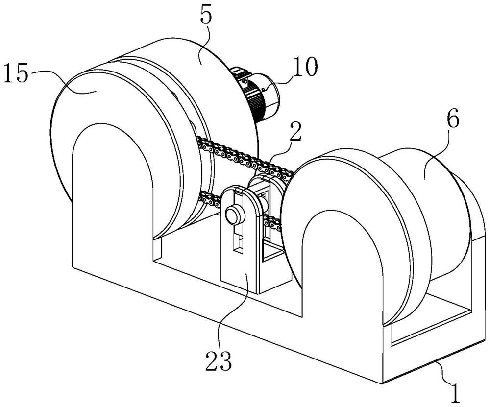
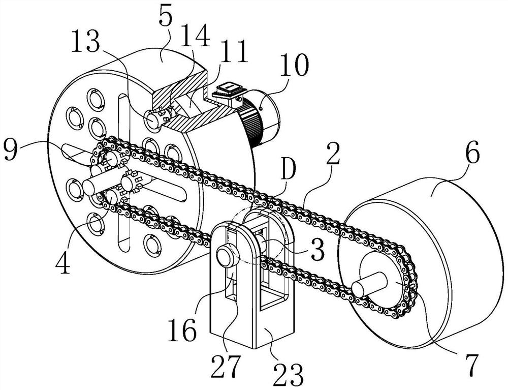

Image

  • Differential gear
  • Differential gear
  • Differential gear

Examples


Embodiment approach

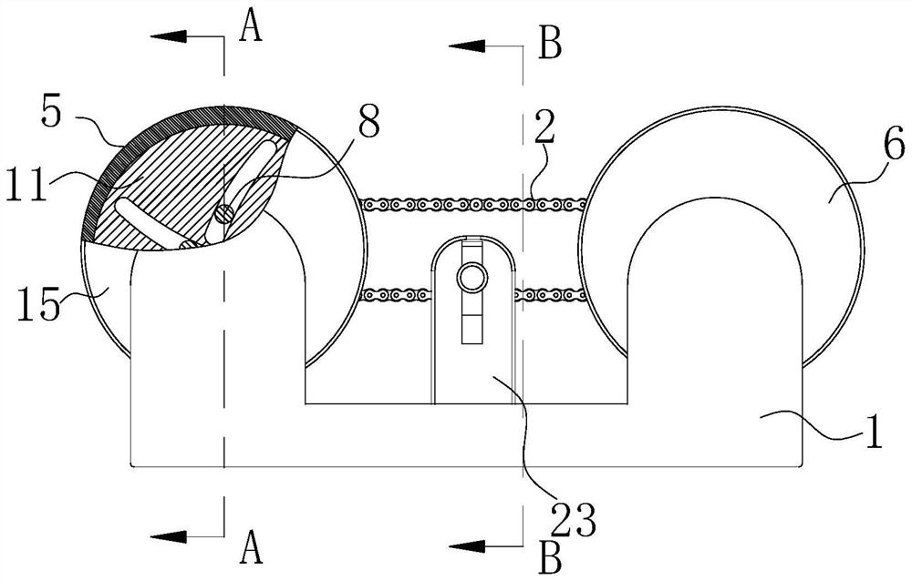
[0029] As an embodiment of the present invention, a rotating cavity is opened inside the drive plate 5 ; a guide plate 11 is rotatably connected to the inside of the rotating cavity; Guide grooves are provided, and the sliders 8 are slidably connected to the inside of the corresponding guide grooves; the rear end surface of the rotating cavity is fixedly connected with the second motor 12 , and the output shaft of the second motor 12 is fixedly connected with the guide plate 11 . When working, by setting the guide plate 11, through the rotation of the control element, that is, the second motor 12, the second motor 12 will drive the guide plate 11 to rotate, and the slider 8 on the surface will be driven by the guide plate 11 and the inside of the corresponding guide groove Sliding, by designing the guide groove as an involute trend structure, and cooperating with the sliding block 8 inside the sliding groove on the surface of the driving disc 5, the automatic adjustment of the ...


PUM


Abstract

The invention belongs to the technical field of transmission equipment, in particular to differential transmission equipment; it includes a bracket, a chain and a supporting gear; the inner part of the bracket close to the left and right side surfaces of the bracket is rotatably connected with a rotating column; A driving disc is fixedly connected to the surface of the column; a driven disc is fixedly connected to the surface of the rotating column at the right position; a driven gear is fixedly connected to the front end surface of the driven disc; the upper end surface of the driving disc is provided with Evenly arranged adjusting gears; a chain is commonly connected between the adjusting gear and the driven gear; a supporting gear is arranged between the adjusting gear and the driving gear; the invention effectively realizes the transmission ratio of the chain differential transmission mode. The quick adjustment avoids the need to switch the transmission gear during the adjustment process, greatly reduces the risk of the chain falling off when the transmission ratio is switched, reduces the switching jam and the jamming damage to the chain, and improves the service life of the differential transmission equipment.

Description

technical field [0001] The invention belongs to the technical field of transmission equipment, in particular to differential transmission equipment. Background technique [0002] In the field of machinery, transmission equipment plays an important role. In the process of transmitting the power output from the motor or other power source to the executive components, due to the fast speed of the motor, it is necessary to decelerate and use differential transmission equipment. At the same time, when other power sources are outputting power, in order to reduce the output force of the power source and adjust the rotational speed, a differential transmission device will also be used. [0003] According to CN110762165A transmission chain, the purpose of the invention is to provide a transmission chain, which has the advantages of improving the bonding between components, thereby effectively reducing the loss of wear and excessive stretching during transmission, and greatly improvin...

Claims


Application Information

Patent Timeline
Patent Type & Authority Patents(China)
IPC IPC(8): F16H9/24F16H7/08F16H55/30
CPCF16H9/24F16H7/08F16H55/303F16H2007/0806F16H2007/0844
Inventor 朱夏青
Owner NANJING YUSHENG ROBOT CO LTD
Learn More