
Cavitation pipe liquid flow test method

A test method and cavitation technology, applied in fluid dynamics test, machine/structural component test, measuring device, etc., can solve problems such as high complexity of cavitation pipe liquid flow test system, and reduce inlet pressure and outlet pressure. The effect of pressure requirements

Active Publication Date: 2021-04-02
BEIJING XINGJI RONGYAO SPACE TECH CO LTD +1
View PDF5 Cites 0 Cited by
  • Summary
  • Abstract
  • Description
  • Claims
  • Application Information

AI Technical Summary

Problems solved by technology

[0005] Therefore, the technical problem to be solved by the present invention is to overcome the high complexity of the existing cavitation pipe liquid flow test system, thereby providing a cavitation pipe liquid flow test method

Method used

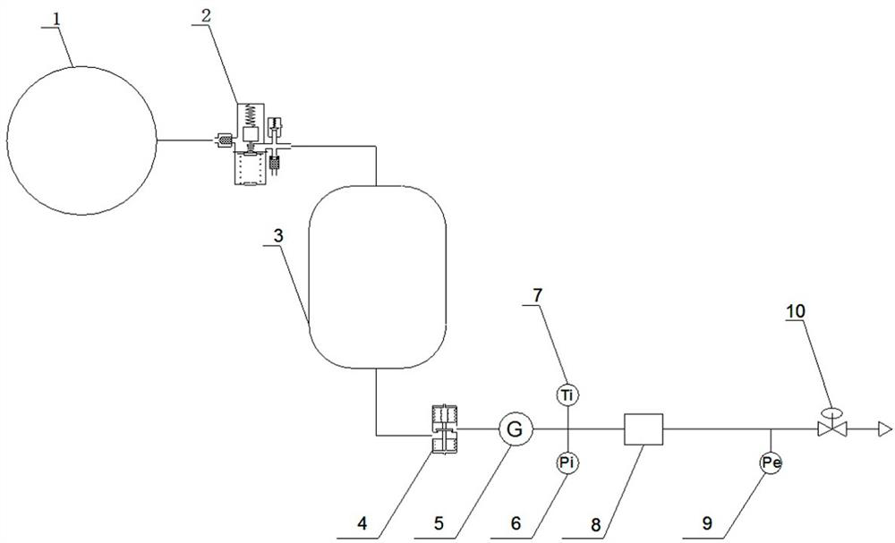
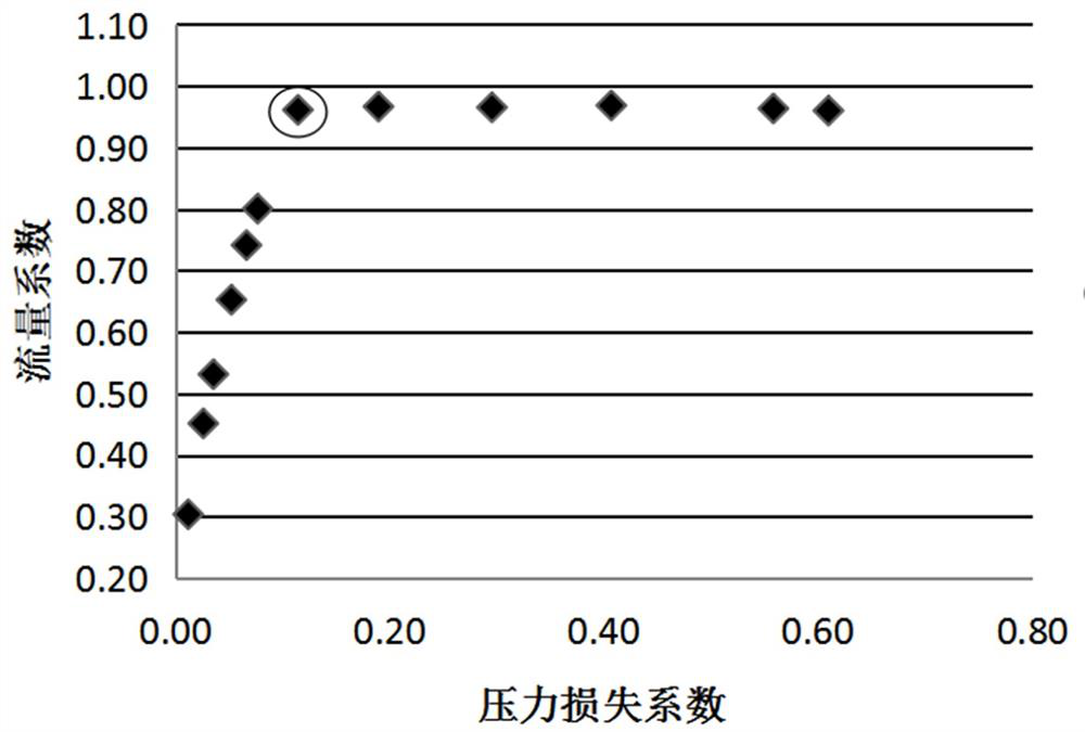

Image

  • Cavitation pipe liquid flow test method
  • Cavitation pipe liquid flow test method
  • Cavitation pipe liquid flow test method

Examples


Embodiment 1

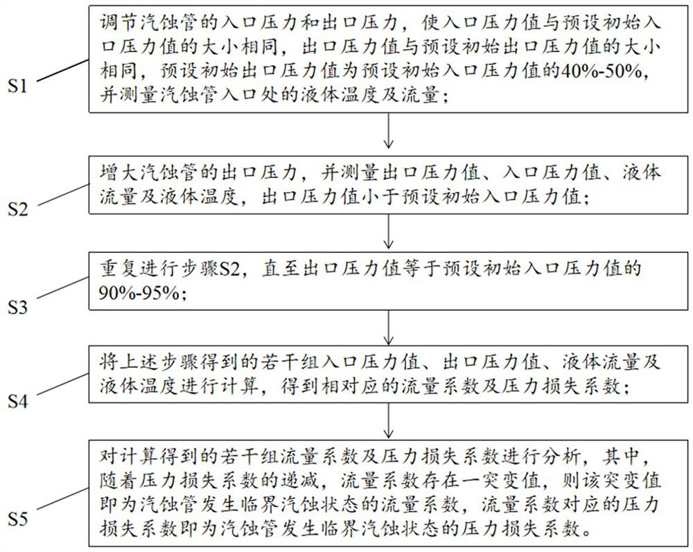
[0050] Such as figure 2 As shown, the present embodiment provides a cavitation pipe liquid flow test method, comprising the following steps:

[0051] S1. Adjust the inlet pressure and outlet pressure of the cavitation pipe so that the inlet pressure value is the same as the preset initial inlet pressure value, the outlet pressure value is the same as the preset initial outlet pressure value, and the preset initial outlet pressure value is the preset value. Set 40%-50% of the initial inlet pressure value, and measure the liquid temperature and flow at the inlet of the cavitation pipe;

[0052] S2. Increase the outlet pressure of the cavitation pipe, and measure the outlet pressure value, inlet pressure value, liquid flow rate and liquid temperature, so that the outlet pressure value is less than the preset initial inlet pressure value;

[0053] S3. Repeat step (2) until the outlet pressure value is equal to 90%-95% of the preset initial inlet pressure value;

[0054] S4. Cal...

Embodiment 2

[0089] Such as Figure 4 As shown, the present embodiment provides a cavitation pipe liquid flow test method, comprising the following steps:

[0090] S1. Adjust the inlet pressure and outlet pressure of the cavitation pipe so that the inlet pressure value is the same as the preset initial inlet pressure value, the outlet pressure value is the same as the preset initial outlet pressure value, and the preset initial outlet pressure value is the preset value. Set 90%-95% of the initial inlet pressure value, and measure the liquid temperature and flow at the inlet of the cavitation pipe;

[0091] S2. Reduce the outlet pressure of the cavitation pipe, and measure the outlet pressure value, inlet pressure value, liquid flow rate and liquid temperature;

[0092] S3. Repeat step (2) until the outlet pressure value is equal to 45%-50% of the preset initial inlet pressure value;

[0093] S4. Calculate several sets of inlet pressure values, outlet pressure values, liquid flow rates an...


PUM


Abstract

The invention provides a cavitation pipe liquid flow test method which comprises the following steps: firstly, adjusting the inlet pressure and the outlet pressure of a cavitation pipe to be respectively the same as a preset initial inlet pressure value and a preset initial outlet pressure value, and measuring the temperature and the flow of liquid at the inlet of the cavitation pipe; gradually adjusting the outlet pressure of the cavitation pipe, and measuring the outlet pressure value, the inlet pressure value, the liquid flow and the liquid temperature; calculating a plurality of groups ofdata obtained in the above steps to obtain corresponding flow coefficients and pressure loss coefficients; and analyzing the plurality of groups of flow coefficients and pressure loss coefficients toobtain the flow coefficients and the pressure loss coefficients of the cavitation pipe in the critical cavitation state. The inlet pressure of the cavitation pipe does not need to be strictly limitedin the test process so that the normal operation of a liquid flow experiment can be ensured without arranging intelligent automatic adjusting equipment, the complexity of the test system is reduced, and the cost of the test system is reduced.

Description

technical field [0001] The invention relates to the technical field of liquid rockets, in particular to a cavitation tube liquid flow test method. Background technique [0002] The dimensional tolerances and assembly tolerances of various components in the liquid rocket engine will cause deviations in parameters such as turbine efficiency, pump characteristics, gas-liquid flow path and pressure drop of the engine nozzle, resulting in the dispersion of engine performance parameters. In order to solve the above problems, adjustment elements such as cavitation tubes are usually installed in the engine pipeline, and the propellant flow rate of the engine is adjusted by changing the throat size of the cavitation tube, so as to achieve the purpose of adjusting the thrust and mixing ratio. [0003] Before the cavitation pipe is selected, it is necessary to conduct a liquid flow test on the cavitation pipe to obtain the characteristic parameters of the cavitation pipe under the work...

Claims


Application Information

Patent Timeline
IPC IPC(8): G01M10/00
CPCG01M10/00
Inventor 张志浩于新宇彭小波张玺
Owner BEIJING XINGJI RONGYAO SPACE TECH CO LTD
Learn More