Production process of audio earphone pins

An audio earphone and production process technology, which is applied to the production process field of audio earphone pins, can solve the problems of long injection molding channel, less glue, waste products, etc., and achieve the effects of improving production efficiency, improving uniformity, and improving yield

Active Publication Date: 2017-11-17
JOLLYKING ELECTRONICS
View PDF6 Cites 1 Cited by
  • Summary
  • Abstract
  • Description
  • Claims
  • Application Information

AI Technical Summary

Problems solved by technology

[0003] During the injection molding process of the existing earphone pin, due to the relatively long length of the second-level middle tube 2 or the third-level middle tube 3 , the PIN needle 1 is connected to the second-level middle tube 2, and the second-level middle tube 2 is connected to the third-level middle tube. The injection molding channel formed between the middle tubes 3 is long, and the plastic cannot fill the entire injection molding channel well during the injection molding process, and it is prone to lack of glue and less glue, resulting in waste products

Method used


Image

  • Production process of audio earphone pins
  • Production process of audio earphone pins
  • Production process of audio earphone pins

Examples


Embodiment 1

[0062] A production process for an audio earphone pin, comprising the following processing steps:

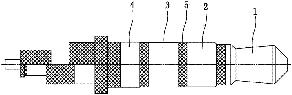
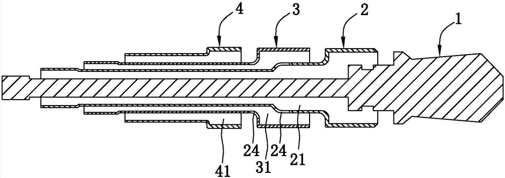
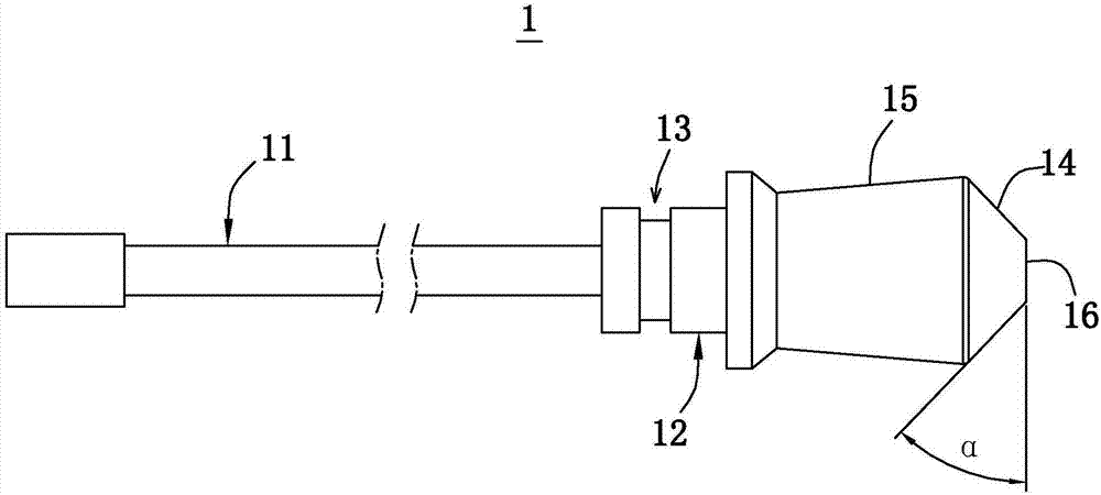
[0063] Step A: See figure 1 , respectively independently process the PIN needle 1, the second-level middle tube 2, the third-level middle tube 3 and the fourth-level large sleeve 4. The details of PIN pin 1 include the following steps:

[0064] Step A1-1, turning the small outer diameter: Turning one end of the PIN pin 1 according to the designed size;

[0065] Step A1-2, slotting: open an annular groove 13 on the outer wall of the PIN needle 1;

[0066] Step A1-3, turning large outer diameter: the same end of PIN pin 1 is turned according to the design size;

[0067] Step A1-4, chamfering: turning a chamfer 14 with α equal to 45° at the other end of the PIN pin 1;

[0068] Step A1-5, turning the inclined surface and flattening: turning the inclined surface 15 according to the design size, and completing the end turning process at the same time.

[0069] Both the second-sta...

Embodiment 2

[0097] A production process for audio earphone pins, the difference from Example 1 is that 8 times of stamping and stretching are carried out in step A2-2, 7 times of stamping and stretching are carried out in step A3-2, and the injection molding temperature in step B is 226°C , The mold clamping injection duration is 7s.

Embodiment 3

[0099] A production process of an audio earphone pin, the difference from the first embodiment is that in step B, the clamping pressure is controlled at 101 bar, and the injection molding temperature is 220°C.


PUM


Abstract

The invention discloses a production process of audio earphone pins. The production process comprises the following steps: A. a PIN, a second-grade middle pipe, a third-grade middle pipe and a fourth-grade large sleeve are independently machined, respectively; and in the machining process of the second-grade middle pipe and/or the third-grade middle pipe, feed holes communicating with the internals are formed on the pipe walls and near one sides of the large ends; B. the Pin, the second-grade middle pipe, the third-grade middle pipe and the fourth-grade large sleeve are assembled to put in a mold hole of a mold bar for injection molding; and plastic is fed from one sides far from the large ends; and C. the earphone pings molded by injection are taken out from the mold bar for unloading and trimming; part of the plastic can be fed in an injection molding channel of the inner layer from a feed hole for feeding; and as the internal injection molding channel and the external are consistent in air pressure through the feed hole, the plastic is effectively prevented from passing through the outer-layer injection molding channel, meanwhile, the injection molding pressure can be reduced, and the yield is increased.

Description

technical field [0001] The invention relates to an audio plug connector, in particular to a production process of an audio earphone pin. Background technique [0002] Mobile phones, MP3, MP4 or handheld computers and the like on the market are all provided with audio or video jacks, which are used to connect audio or video earphone pins. Existing headphone pins such as figure 1 Shown is a 3.5mm four-level pin, including PIN pin 1, second-level middle tube 2, third-level middle tube 3, and fourth-level large sleeve 4. The four-level metal parts are assembled in sequence and finally injection-molded, plastic The injection molding channel formed between two adjacent metal levels will be slowly filled and the insulating part 5 will be formed after solidification. The insulating part 5 can prevent short circuit after the two adjacent metal levels are in contact with each other. [0003] During the injection molding process of the existing earphone pin, due to the relatively lon...

Claims


Application Information

Patent Timeline
Patent Type & Authority Applications(China)
IPC IPC(8): B29C45/14B21D35/00B29L31/36
CPCB21D35/002B29C45/14B29C45/1418B29L2031/36
Inventor 俞红春
Owner JOLLYKING ELECTRONICS
Why Eureka
Try Eureka