Operation method of automobile fuel gas electric control operation control valve

An operation method and operation control technology, applied in the direction of valve operation/release device, valve details, safety valve, etc., can solve problems such as inability to adjust pressure and unsmooth gas delivery.

Inactive Publication Date: 2018-03-13
SICHUAN SENJIE GAS EQUIP CO LTD
View PDF9 Cites 1 Cited by
  • Summary
  • Abstract
  • Description
  • Claims
  • Application Information

AI Technical Summary

Problems solved by technology

[0004] When the pressure in the electronically controlled gas injection system is high, the existing regulating device cannot effectively adjust the pressure, resulting in unsmooth gas delivery

Method used


Image

  • Operation method of automobile fuel gas electric control operation control valve

Examples


Embodiment 1

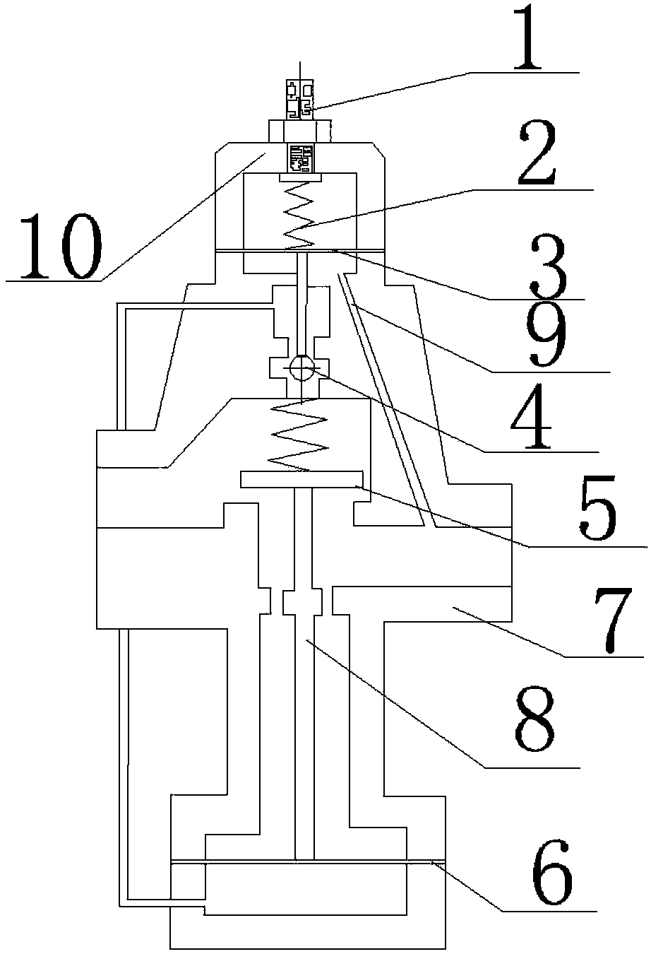
[0019] Such as figure 1 As shown, an operation method of an automobile gas electric control operation control valve includes an adjusting screw 1, an adjusting spring 2, a small diaphragm 3, an auxiliary valve disc 4, a main valve disc 5, and a large diaphragm 6, and the adjusting screw 1 passes through The top cover of the valve seat 10 is connected with the adjustment spring 2, the lower end of the adjustment spring 2 is connected with the auxiliary valve disc 4 through the small diaphragm 3, the auxiliary valve disc 4 is connected with the main valve disc 5 through the spring, and the lower end of the main valve disc 5 is connected with Connecting pipe 8, connecting pipe 8 is connected with large diaphragm 6, and described adjusting spring 2, small diaphragm 3, secondary valve flap 4, main valve flap 5, large diaphragm 6 are all located in valve seat 10.

[0020] Wherein, the chamber where the auxiliary valve disc is located communicates with the chamber where the large dia...


PUM


Abstract

The invention discloses an operation method of an automobile fuel gas electric control operation control valve. The method comprises the steps that an adjusting screw is unscrewed to open an auxiliaryvalve clack, fuel gas enters the position below a large membrane, the large membrane is moved to open a main valve clack, gas enters the position below a small membrane at the same time, and outlet pressure is adjusted. According to the technical scheme, inlet pressure of fluid is pressed by one half through the throttling principle and automatically kept to an adjusting value with certain neededoutlet pressure. A speed reducing valve is mainly applied to steam, gas, water and oil supply systems.

Description

technical field [0001] The invention relates to the technical field of gas, in particular to an operating method for an automobile gas electric control operation control valve. Background technique [0002] With the rapid growth of car ownership, the problems of environmental pollution and shortage of oil resources are becoming more and more serious. To this end, countries around the world are actively developing new energy vehicles. Among them, natural gas vehicles are being popularized and promoted around the world due to their three major characteristics: low emissions, suppression of greenhouse effect, and independence from oil. In our country, many urban buses and taxis have a large number of fuel vehicles that have switched or are switching to compressed natural gas (CNG) or liquefied petroleum gas (LPG). With the rapid increase in the number of gas vehicles in my country, it is imperative to develop gas heaters that match it. [0003] In the electronic control inje...

Claims


Application Information

Patent Timeline
Patent Type & Authority Applications(China)
IPC IPC(8): F16K17/20F16K31/365
CPCF16K17/20F16K31/365
Inventor 何松龙
Owner SICHUAN SENJIE GAS EQUIP CO LTD
Why Eureka
Try Eureka