Method for operating a vacuum pump system and vacuum pump system applying such method

a vacuum pump and vacuum pump technology, applied in the direction of pump control, positive displacement liquid engine, rotary/oscillating piston combination for elastic fluids, etc., can solve the problems of system and control logic not being suitable for all types of applications, control logic creating undesired fluctuations that will affect the user's application, and control logic not being able to avoid the situation in which the system is either under-designed or over-designed, etc. the effect of reducing the pressure of the inl

Active Publication Date: 2021-09-07
ATLAS COPCO AIRPOWER NV
View PDF17 Cites 2 Cited by
  • Summary
  • Abstract
  • Description
  • Claims
  • Application Information

AI Technical Summary

Benefits of technology

[0022]Moreover, by starting a secondary vacuum pump at a second predetermined startup load, the inlet pressure can be reduced sequentially and only to such extent to meet the user's demand. Accordingly, if the vacuum pump system comprises a high capacity pump, such pump will not run at a higher load than requested by the user's application. Consequently, a high capacity pump can achieve a high, medium or low capacity in an efficient way, without having the risk of having an under-designed or overdesigned system to match the flow and accordingly the demand of the user's network.
[0023]By applying the method according to the present invention, the vacuum pump system can be easily adapted to meet different vacuum demands, and can therefore be used for different applications without the need of a manual intervention.
[0024]Moreover, because the vacuum pumps are not started at a maximum load and because the method according to the present invention divides the secondary vacuum pumps into groups and operates them depending on the priority assigned, an equal wear of all the vacuum pumps can be achieved.
[0025]Furthermore, depending on where a user of a vacuum pump system according to the present invention is located geographically, the costs incurred by the functioning of the vacuum pump system can differ according to, for example: the price of electricity, environmental conditions, or even ease of accessibility for maintenance. Consequently, in some geographical areas an energy optimization can be required, while in others a wear optimization can be a better solution.

Problems solved by technology

Such a system and control logic is not suitable for all types of applications.
If we take the example in which the variable speed pump is of a higher capacity than a fixed speed pump, such a control logic can create undesired fluctuations that will affect the user's application.
Moreover, such a control logic will not avoid the situation in which the system is either under-designed or over-designed for the application to which it is connected, since it considers the startup of a fixed speed pump equivalent with the functioning capability of a variable speed pump running at maximum output.
Furthermore, such a control logic would not allow a user of the system to control the energy efficiency of the system or to minimize maintenance costs, since the user is not able to influence which of the vacuum pumps is running.

Method used


Image

  • Method for operating a vacuum pump system and vacuum pump system applying such method
  • Method for operating a vacuum pump system and vacuum pump system applying such method
  • Method for operating a vacuum pump system and vacuum pump system applying such method

Examples


Embodiment Construction

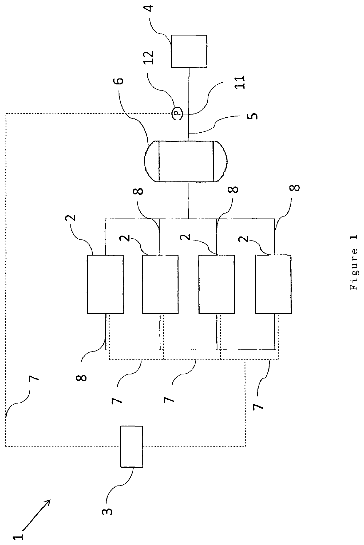
[0040]FIG. 1 illustrates a vacuum pump system 1 comprising a plurality of vacuum pumps 2 and a control unit 3 controlling said vacuum pumps 2. The system is being further connected to a user of vacuum 4 within an external user's network through a flow conduit 5. The vacuum pump system 1 can further comprise a buffer vessel 6 connected to an inlet 11 of the vacuum pump system for receiving fluid. Such a buffer vessel 6 increases the stability of the vacuum pump system 1 because it assures a volume of fluid immediately ready for the user's network 4.

[0041]Said control unit 3 is controlling said vacuum pumps 2 through an electrical connection 7.

[0042]In FIG. 1 an example of a vacuum pump system according to the present invention is illustrated, such system comprising four vacuum pumps 2, interconnected by a flow conduit 8.

[0043]The present invention should not be limited to a vacuum pump system 1 comprising only four vacuum pumps 2. The method according to the present invention is appl...


PUM


Abstract

A method of operating a vacuum pump system, the method including the steps of: operating a primary vacuum pump having a variable speed motor; connecting at least two secondary vacuum pumps in parallel with said primary vacuum pump; dividing the secondary vacuum pumps in groups, each group including at least one secondary vacuum pump; and assigning a priority for each of said groups. The method further includes the steps of measuring the inlet pressure p1, comparing the measured inlet pressure p1 with a predetermined pressure value p0, and if p1 is higher than p0, starting the secondary vacuum pump at a first predetermined startup load Sstartup,1 if it includes a fixed speed motor, and/or starting the secondary vacuum pump at a second predetermined startup load Sstartup,2, if it includes a variable speed motor.

Description

[0001]This invention relates to a method of operating a vacuum pump system, the method comprising the steps of: operating a primary vacuum pump comprising a variable speed motor; connecting at least two secondary vacuum pumps in parallel with said primary vacuum pump, each of the at least two secondary vacuum pumps comprising a motor; dividing the secondary vacuum pumps in groups, each group comprising at least one secondary vacuum pump, and assigning a priority for each of said groups.BACKGROUND OF THE INVENTION[0002]Systems comprising a plurality of vacuum pumps exist, like for example the system disclosed in U.S. Pat. No. 5,522,707 B in the name of Metropolitan Industries, Inc. The system described therein uses a controller unit for starting an additional pump when the demand for vacuum increases. When a variable speed vacuum pump reaches the maximum output, the controller unit starts a fixed speed vacuum pump and stops the variable speed vacuum pump.[0003]Such a system and contr...

Claims


Application Information

Patent Timeline
Patent Type & Authority Patents(United States)
IPC IPC(8): F04C28/02F04B49/06F04C23/00F04C25/02F04B49/08F04B41/06F04B37/14
CPCF04C28/02F04B37/14F04B41/06F04B49/065F04B49/08F04C23/001F04C25/02
Inventor COECKELBERGS, JOERI
Owner ATLAS COPCO AIRPOWER NV
Why Eureka
Try Eureka