
Low noise discharge nozzle

Pending Publication Date: 2022-11-10
CARRIER CORP
View PDF0 Cites 0 Cited by
  • Summary
  • Abstract
  • Description
  • Claims
  • Application Information

AI Technical Summary

Benefits of technology

The invention is a nozzle assembly for a fire suppression system that reduces the noise level from the nozzle. It achieves this by using a plurality of exit orifices in the nozzle portion to direct the flow of fire extinguishing agent in a way that reduces the pressure level and noise. The nozzle also includes a perforated filter member that reduces the pressure of the fire extinguishing agent before it reaches the nozzle. Overall, this invention helps to make fire suppression systems more efficient and effective while reducing noise levels.

Problems solved by technology

Downtime can damage the reputation of a data center and result in the loss of customers.
That is, sound pressure can cause vibration induced damage or disruptions to an HDD.
Unfortunately, inert gas fire suppression systems typically used to protect the server rooms that house this type of equipment in a data center, utilize nozzles that can produce sound levels which may have an adverse effect on this noise sensitive hardware.
Indeed, some common nozzles generate noise levels in excess of 130 dB, which creates an unacceptable risk of lost data and operation time for a data center.

Method used


Image

  • Low noise discharge nozzle
  • Low noise discharge nozzle
  • Low noise discharge nozzle

Examples


Embodiment Construction

[0035]A detailed description of one or more embodiments of the disclosed apparatus and method are presented herein by way of exemplification and not limitation with reference to the Figures.

[0036]The term “about” is intended to include the degree of error associated with measurement of the particular quantity based upon the equipment available at the time of filing the application.

[0037]The terminology used herein is for the purpose of describing particular embodiments only and is not intended to be limiting of the present disclosure. As used herein, the singular forms “a”, “an” and “the” are intended to include the plural forms as well, unless the context clearly indicates otherwise. It will be further understood that the terms “comprises” and / or “comprising,” when used in this specification, specify the presence of stated features, integers, steps, operations, elements, and / or components, but do not preclude the presence or addition of one or more other features, integers, steps, ...


PUM


Abstract

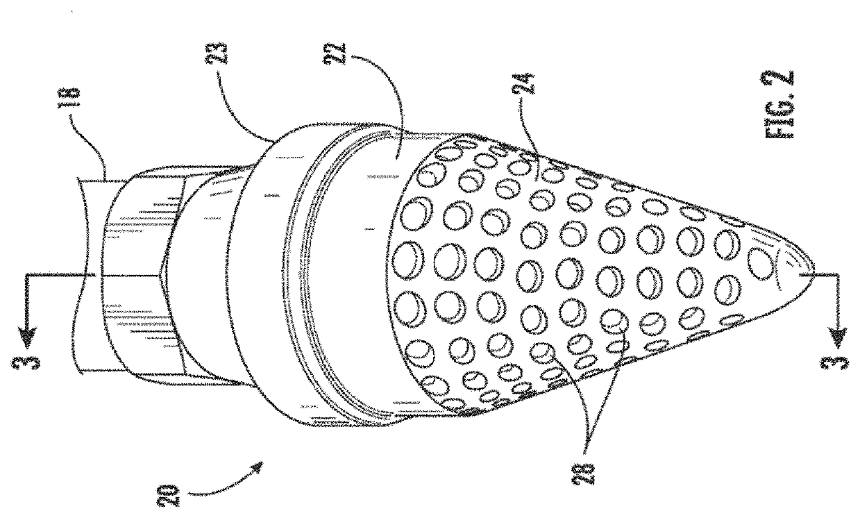
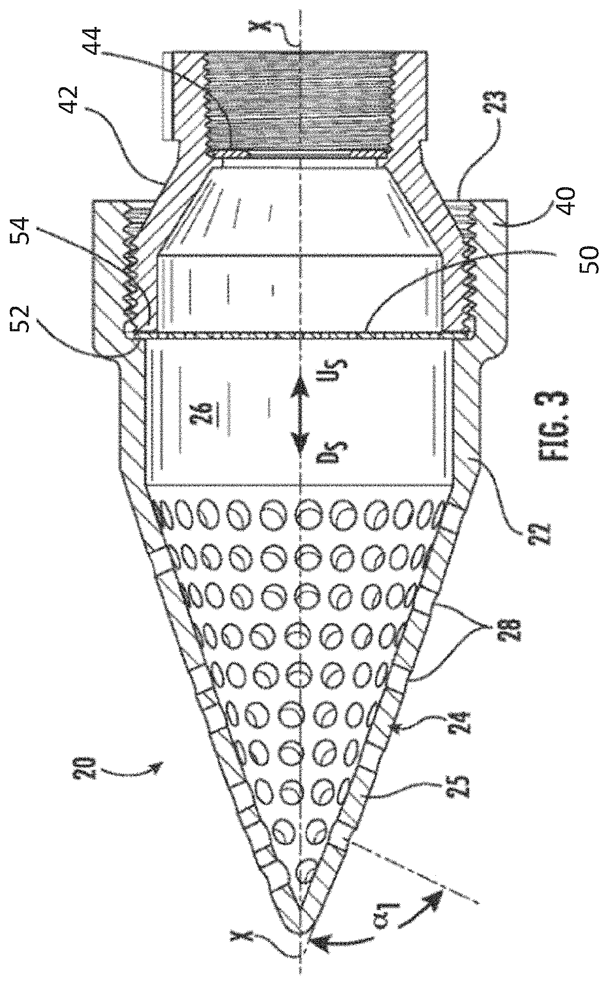
A nozzle assembly for a fire suppression system includes a body having an inlet end for receiving a flow of fire extinguishing agent from the fire suppression system at an inlet pressure and a nozzle portion extending from the body. The nozzle portion includes an interior cavity having an outlet end, a center body arranged within the interior cavity adjacent the outlet end, and a plurality of exit orifices formed in an outer wall of the nozzle portion, in communication with the interior cavity, for vectoring the flow of fire extinguishing agent exiting therefrom and to reduce a noise level of the nozzle assembly. At least one perforated filter member is positioned upstream from the plurality of exit orifices formed in the nozzle portion, for reducing the inlet pressure of the flow of fire extinguishing agent.

Description

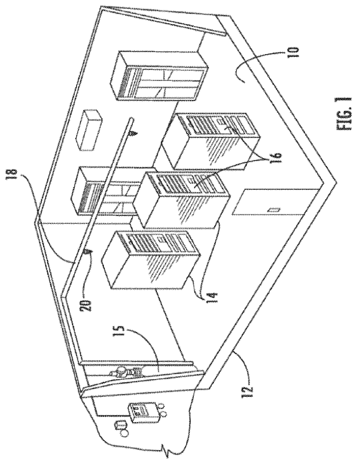
BACKGROUND[0001]The subject invention is directed to fire suppression systems, and more particularly, to a low noise nozzle assembly for use with a fire suppression system deployed in a data center.[0002]Data centers are relied upon to store and distribute valuable information across many industries. Industry demands that these data centers remain continuously functional. Downtime can damage the reputation of a data center and result in the loss of customers. The valuable information handled by data centers is primarily stored on magnetic Hard Disk Drives (HDDs). These hardware devices have a known sensitivity to sound. That is, sound pressure can cause vibration induced damage or disruptions to an HDD.[0003]Unfortunately, inert gas fire suppression systems typically used to protect the server rooms that house this type of equipment in a data center, utilize nozzles that can produce sound levels which may have an adverse effect on this noise sensitive hardware. Indeed, some common n...

Claims


Application Information

Patent Timeline
IPC IPC(8): A62C31/05A62C99/00
CPCA62C31/05A62C99/0018
Inventor KOUSHIK, SUDARSHAN N.MCCORMICK, DUANE C.
Owner CARRIER CORP
Learn More