Oil scavenge system

Active Publication Date: 2020-07-23
ROLLS ROYCE PLC
View PDF0 Cites 1 Cited by
  • Summary
  • Abstract
  • Description
  • Claims
  • Application Information

AI Technical Summary

Benefits of technology

[0021]Scavenging oil using a two-stage scavenging method in accordance with the fourth aspect, using the at least one primary scavenge pump and the secondary scavenge pump, may enable the oil scavenge system to provide a high outlet pressure from a low inlet pressure, whilst preventing cavitation in either or both of the at least one primary scavenge pump and the secondary scavenge pump (where cavitation may be caused by low inlet pressures and high outlet pressures).
[0022]A two-stage oil scavenging met

Problems solved by technology

However, for some gas turbine engines (for example, gas turbine engines with core mounted accessories and/or a fan case mounted oil tank), the ability to install the required oil filtering system on the discharge side of the oil feed pump can cause issues with regard to the space available to install the filter.
However, alternatively trying to install an oil filtering system on the inlet side of an oil feed pump (e.g., between the oil tank and pump inlet) further reduces the inlet pressure of the oil feed pump, which is undesirable, as this may result in pump cavitation and d

Method used


Image

  • Oil scavenge system
  • Oil scavenge system
  • Oil scavenge system

Examples


Embodiment Construction

[0064]Aspects and embodiments of the present disclosure will now be discussed with reference to the accompanying figures. Further aspects and embodiments will be apparent to those skilled in the art.

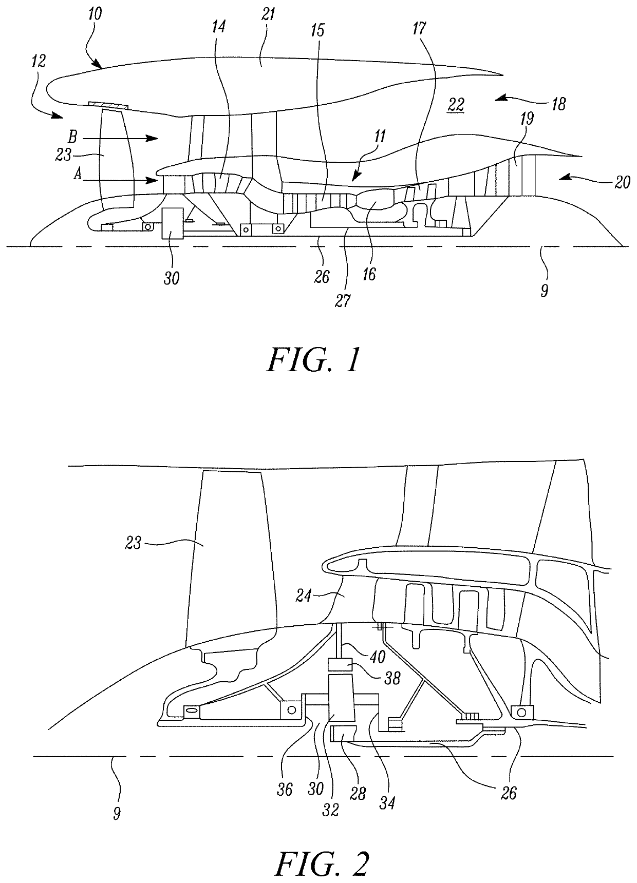
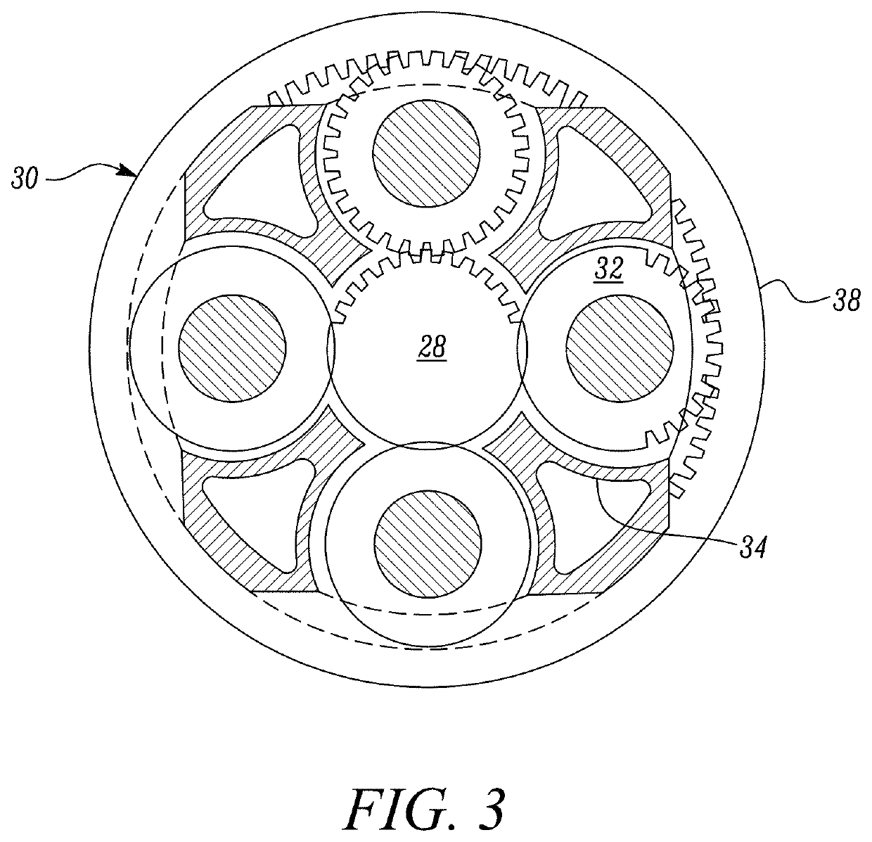
[0065]FIG. 1 illustrates a gas turbine engine 10 having a principal rotational axis 9. The engine 10 comprises an air intake 12 and a propulsive fan 23 that generates two airflows: a core airflow A and a bypass airflow B. The gas turbine engine 10 comprises a core 11 that receives the core airflow A. The engine core 11 comprises, in axial flow series, a low pressure compressor 14, a high-pressure compressor 15, combustion equipment 16, a high-pressure turbine 17, a low pressure turbine 19 and a core exhaust nozzle 20. A nacelle 21 surrounds the gas turbine engine 10 and defines a bypass duct 22 and a bypass exhaust nozzle 18. The bypass airflow B flows through the bypass duct 22. The fan 23 is attached to and driven by the low pressure turbine 19 via a shaft 26 and an epicyclic gearbox 3...


PUM


Abstract

An oil scavenge system for a gas turbine engine comprising an oil tank and at least one bearing chamber. The oil scavenge system comprises at least one primary scavenge pump, a manifold, a secondary scavenge pump, a deaerator and a filter unit. The at least one primary scavenge pump is configured to pump oil from the at least one bearing chamber to the manifold whilst raising the pressure of the oil from a starting pressure to a first pressure elevated with respect to the starting pressure. The manifold is pressurised to substantially maintain the oil at said first pressure. The secondary scavenge pump is configured to pump oil from the manifold at the first pressure and to raise the pressure of the oil to a second pressure elevated with respect to the first pressure before pumping the oil to the deaerator and through the filter unit to the oil tank.

Description

CROSS-REFERENCE TO RELATED APPLICATIONS[0001]This specification is based upon and claims the benefit of priority from United Kingdom patent application number GB 1900906.7 filed on Jan. 23, 2019, the entire contents of which are incorporated herein by reference.BACKGROUNDField of the Disclosure[0002]The present disclosure relates to an oil scavenge system for a gas turbine engine, a method of scavenging oil and a gas turbine engine.Description of the Related Art[0003]Gas turbine engines are typically full flow recirculatory systems requiring adequate lubrication and cooling of all engine bearings, gears and drive splines under all foreseeable operating conditions.[0004]Lubricant scavenge systems, more specifically oil scavenge systems (such as an oil scavenge pump), in gas turbine engines remove lubricant from a sump area within the engine adjacent engine components (typically bearings) which require constant lubrication during engine operation.[0005]Traditionally oil filtering syst...

Claims


Application Information

Patent Timeline
IPC IPC(8): F01D25/20F16N7/40
CPCF16N7/40F05D2260/98F16N2210/02F01D25/20F16N31/00F16N31/02F16N39/06F16N39/002F02C7/06F16N2039/007F16N2210/08F05D2260/602F01M1/10F01M2001/123Y02T50/60
Inventor DAVIES, NEIL J
Owner ROLLS ROYCE PLC
Why Eureka
Try Eureka