
Double-shaft driving compressor system adopting non-contact type shaft coupler

A compressor system and dual-shaft drive technology, applied in the field of compressors, can solve the problems of not being able to achieve sealing and no leakage, not being able to achieve no oil, and low gas outlet pressure, so as to solve the problem of medium leakage, high work efficiency, and low gas outlet pressure. high effect

Pending Publication Date: 2020-11-17
山东凯格瑞森能源科技有限公司
View PDF0 Cites 0 Cited by
  • Summary
  • Abstract
  • Description
  • Claims
  • Application Information

AI Technical Summary

Problems solved by technology

In the existing technology, the direct-connection drive method is generally adopted, and the shaft seal alone cannot be completely sealed without leakage; the compressor is lubricated with lubricating oil, and the lubricating oil will enter the medium as the pressure changes, which cannot achieve true sealing. Oil-free; conventional single-shaft compressors have problems such as low efficiency and low outlet pressure

Method used


Image

  • Double-shaft driving compressor system adopting non-contact type shaft coupler
  • Double-shaft driving compressor system adopting non-contact type shaft coupler
  • Double-shaft driving compressor system adopting non-contact type shaft coupler

Examples


Embodiment 1

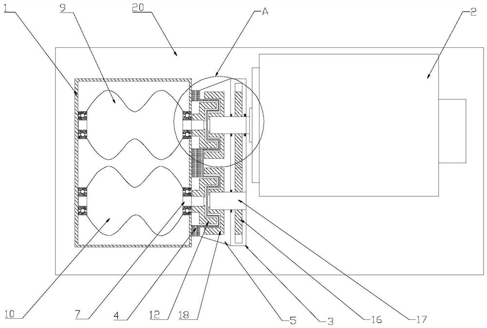
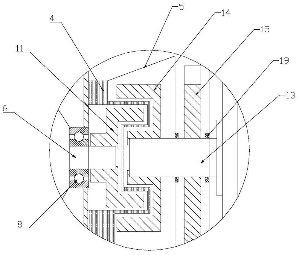
[0037] Such as Figure 1-3As shown, a dual-shaft driven compressor system using a non-contact coupling, the described dual-shaft driven compressor system includes a compressor 1, a motor 2, a gear chamber 3, a sealing cover 4 and a protective cover 5, the The inside of the compressor 1 is provided with a driving rotor shaft 6 and a driven rotor shaft 7, the driving rotor shaft 6 is connected to the compressor 1 through a grease bearing 8, and the driven rotor shaft 7 is connected to the compressor 1 Connected by a grease bearing 8, the middle part of the driving rotor shaft 6 is fixedly connected with the driving rotor blade 9, the middle part of the driven rotor shaft 7 is fixedly connected with the driven rotor blade 10, and one end of the driving rotor shaft 6 is fixedly connected with A driven-side driving-end coupling 11, one end of the driven rotor shaft 7 is fixedly connected with a driven-side driven-end coupling 12;

[0038] The inside of the motor 2 is provided with...

Embodiment 2

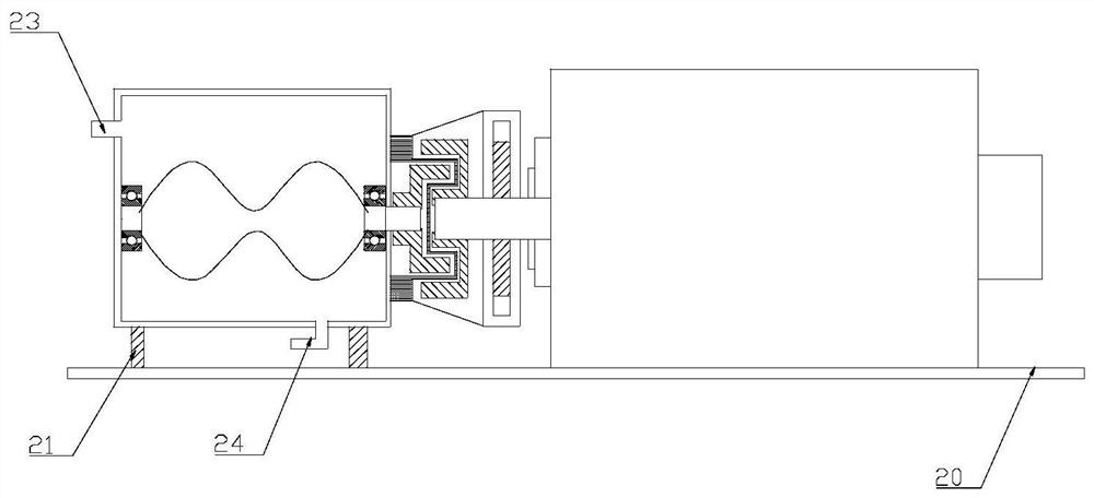
[0042] Such as Figure 4-6 As shown, a dual-shaft driven compressor system using a non-contact coupling, the described dual-shaft driven compressor system includes a compressor 1, a motor 2, a gear chamber 3, a sealing cover 4 and a protective cover 5, the The inside of the compressor 1 is provided with a driving rotor shaft 6 and a driven rotor shaft 7, the driving rotor shaft 6 is connected to the compressor 1 through a grease bearing 8, and the driven rotor shaft 7 is connected to the compressor 1 Connected by a grease bearing 8, the middle part of the driving rotor shaft 6 is fixedly connected with the driving rotor blade 9, the middle part of the driven rotor shaft 7 is fixedly connected with the driven rotor blade 10, and one end of the driving rotor shaft 6 is fixedly connected with A driven-side driving-end coupling 11, one end of the driven rotor shaft 7 is fixedly connected with a driven-side driven-end coupling 12;

[0043] The inside of the motor 2 is provided wit...


PUM


Abstract

The invention relates to a double-shaft driving compressor system adopting a non-contact type shaft coupler. The double-shaft driving compressor system comprises a compressor, a motor, a gear chamber,a sealing cover and a protection cover, wherein a driving rotor shaft and a driven rotor shaft are arranged in the compressor; the driving rotor shaft and the driven rotor shaft are connected with the compressor through a lubricating grease bearing; the driving rotor shaft is fixedly connected with a driven side driving end shaft coupler; the driven rotor shaft is fixedly connected with a drivenside driven end shaft coupler; a motor shaft of the motor is fixedly connected with a driving side driving end shaft coupler; a driving side driven shaft is fixedly connected with a driving side driven end shaft coupler; and the driving side driving end shaft coupler, the driven side driven end shaft coupler, the driving side driving end shaft coupler and the driving side driven end shaft couplerare made of permanent magnet materials. A non-direct-connection driving manner is adopted so that oil-free and leakage-free effects are realized fundamentally; and the double-shaft driving compressorsystem is applicable to a double-shaft compressor, and is high in air outlet pressure and working efficiency.

Description

technical field [0001] The invention relates to a double-shaft drive compressor system using a non-contact shaft coupling, which belongs to the technical field of compressors. Background technique [0002] Compressor is a driven fluid machine that upgrades low-pressure gas to high-pressure gas. It is widely used in various fields such as fluid transportation, chemical industry, industrial gas supply, and automobile industry. [0003] Some special fields require the supplied gas to be clean and oil-free. Considering the characteristics of the transmission medium, such as flammable, explosive, toxic, or corrosive, there are also high requirements for the leakage prevention of the supply system. In the existing technology, the direct-connected drive mode is generally adopted, and the shaft seal alone cannot be completely sealed without leakage; the compressor is lubricated with lubricating oil, and the lubricating oil will enter the medium as the pressure changes, which cannot ...

Claims


Application Information

Patent Timeline
Patent Type & Authority Applications(China)
IPC IPC(8): F04C23/02F04C29/00F04C29/02F04C29/12F04C27/00H02K49/10
CPCF04C23/02F04C27/00F04C29/00F04C29/005F04C29/0064F04C29/02F04C29/12H02K49/102
Inventor 刘凯冷承霖姜启海吴超
Owner 山东凯格瑞森能源科技有限公司
Learn More