
Blade-free super-strong efficient high-pressure fan

A high-pressure fan and super-powerful technology, applied in the direction of mechanical equipment, machine/engine, liquid fuel engine, etc., can solve the problems of increased weight and manufacturing process difficulty, decreased efficiency, etc., to achieve low manufacturing accuracy, improve efficiency, and reduce manufacturing costs Falling effect

Inactive Publication Date: 2019-09-03
陈云桥
View PDF0 Cites 0 Cited by
  • Summary
  • Abstract
  • Description
  • Claims
  • Application Information

AI Technical Summary

Problems solved by technology

[0007] In order to increase the air flow and pressure , to meet the higher demand for high-pressure fans, in addition to increasing the diameter and speed of the blades, it has successively developed to single-stage, double-stage, and three-stage impeller high-pressure fans, and the maximum pressure of the high-pressure fan was once refreshed to 230 kPa. However, it also increases the difficulty of weight and manufacturing process, and reduces the efficiency.

Method used


Image

  • Blade-free super-strong efficient high-pressure fan
  • Blade-free super-strong efficient high-pressure fan
  • Blade-free super-strong efficient high-pressure fan

Examples


Embodiment Construction

[0030] In order to make the object, technical solution and advantages of the present invention clearer, the present invention will be further described in detail below in conjunction with the accompanying drawings and specific embodiments.

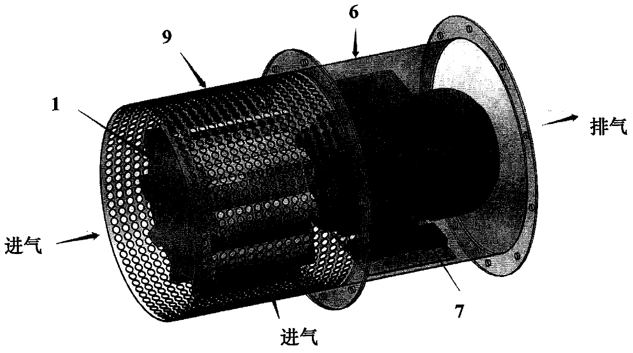
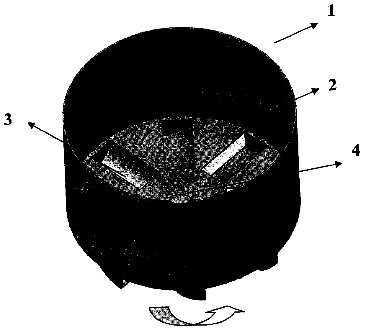
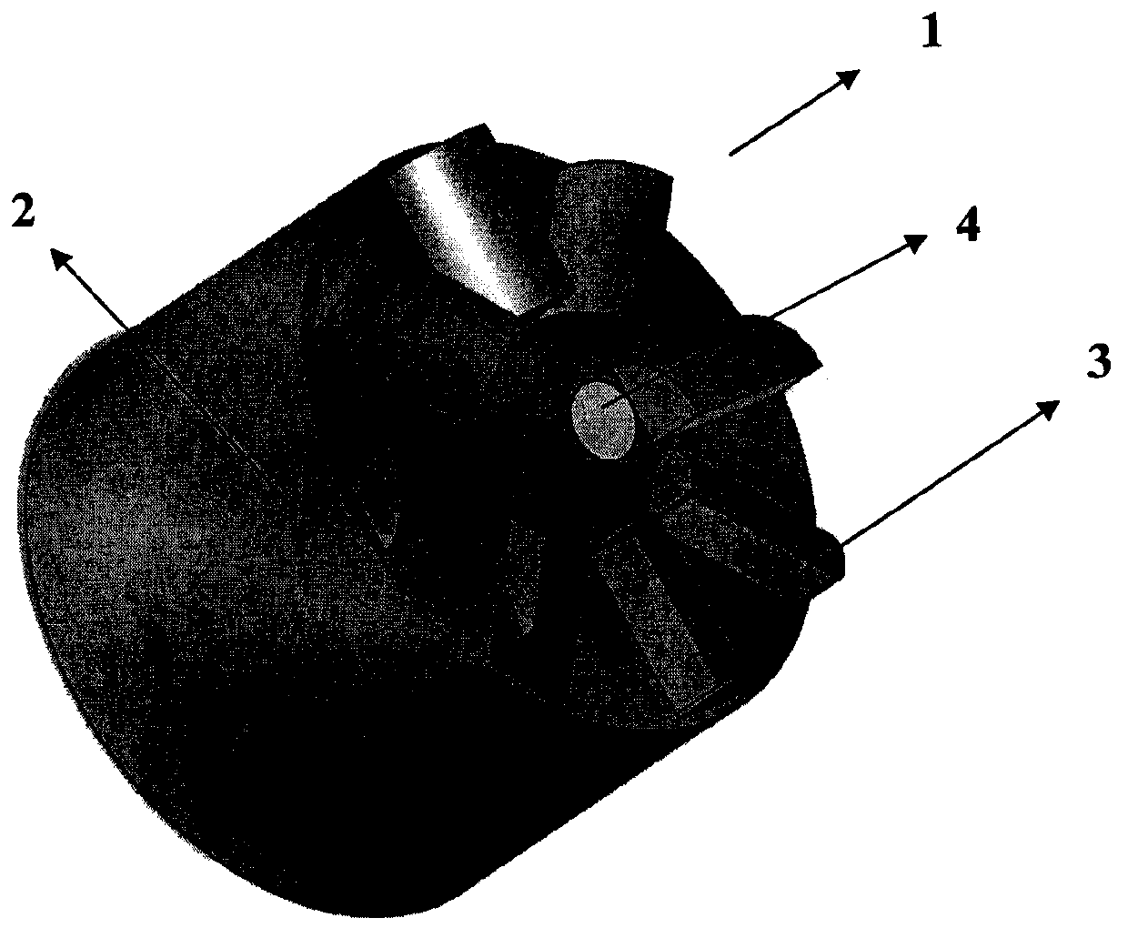
[0031] figure 1 It is a schematic diagram of the overall structure of the fan. As shown in the figure, the blower is composed of a phoenix drum assembly 1, a drive motor 7, a phoenix drum protective cover 9 and a motor fixed protective cover 6. The phoenix drum assembly 1 and the drive motor 7 are respectively installed on the phoenix drum protective cover 9 and the motor fixed In the protective cover 6, the phoenix drum assembly 1 is driven to rotate at a high speed by the drive motor 7 through the drive shaft 5, so that the airflow enters from the front end of the phoenix drum protective cover 9 and the air inlet around the periphery, under the action of the phoenix drum assembly 1. It is discharged at a high speed from the air outlet ...


PUM


Abstract

The invention relates to a blade-free super-strong efficient high-pressure fan. The fan comprises an air drum assembly and a power machine; the air drum assembly is of a cylindrical air drum structure, and a flow guide device is arranged at one closed end of the cylindrical air drum structure; and a cylindrical air drum is driven by the power machine to rotate, air flows enter the cylindrical airdrum in the tangential direction from the flow guide device at one end of the cylindrical air drum, in the cylindrical air drum, and the air flows rotate at a high speed around the inner wall to forma tornado effect and are discharged from the other end port of the cylindrical air drum at a high speed. Due to the fact that the working principle of the fan is different, compared with a common centrifugal fan, the air outlet pressure is high, the air outlet amount is large, the size and the weight are small, and the efficiency of the fan is greatly improved; according to the fan, the requirements on the manufacturing precision and the material are relatively low, the requirement on assembling is loose, and the manufacturing cost is greatly reduced; and 3, due to the special structure of thefan, the requirements on the temperature of a conveyed air inlet medium and the content of particle impurities are relatively loose, and thus the fan can be normally used under various harsh conditions. Due to the performance of the fan, the larger air volume, the larger vacuum degree and the larger air pressure can be generated.

Description

technical field [0001] The invention relates to a centrifugal fan, especially a high-efficiency high-pressure fan with super strong wind pressure without a traditional blade structure. Background technique [0002] The fan is the customary abbreviation for gas compression and gas delivery machinery in my country. The fan relies on the input mechanical energy to improve gas The machinery that pressurizes and discharges gas, commonly referred to as fans, includes ventilators, blowers, wind generators, etc. [0003] Fans are divided into turbine fans and volumetric fans according to their working principles. The turbine fans compress and deliver gas through rotating blades, while the volumetric fans compress and deliver gas by changing the volume of the gas. [0004] Common turbo fans include centrifugal fan and axial flow ventilation. The centrifugal fan uses curved blades to throw the gas to the casing by centrifugal force. The main components of the centrifugal fan are the ...

Claims


Application Information

Patent Timeline
IPC IPC(8): F04D17/06F04D25/08F04D29/28F04D29/70
CPCF04D17/06F04D25/08F04D29/281F04D29/703
Inventor 陈云桥
Owner 陈云桥
Learn More