Optical Lenses and Imaging Equipment

An optical lens and lens technology, applied in the field of imaging lenses, can solve the problems of difficult to meet the requirements of thin and light portable electronic equipment and high-definition imaging, low pixels, large volume, etc. Effect

Active Publication Date: 2021-05-18
JIANGXI LIANYI OPTICS CO LTD
View PDF2 Cites 0 Cited by
  • Summary
  • Abstract
  • Description
  • Claims
  • Application Information

AI Technical Summary

Problems solved by technology

However, most wide-angle lenses currently on the market are large in size and low in pixels, making it difficult to meet the thinning and high-definition imaging requirements of portable electronic devices

Method used


Image

  • Optical Lenses and Imaging Equipment
  • Optical Lenses and Imaging Equipment
  • Optical Lenses and Imaging Equipment

Examples


no. 1 example

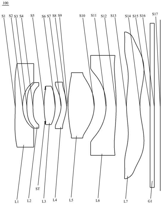
[0073] see figure 1 , which is a schematic structural view of the optical lens 100 provided by the first embodiment of the present invention, the optical lens 100 includes in sequence from the object side to the imaging surface along the optical axis: a first lens L1, a second lens L2, a diaphragm ST, a second lens Three lenses L3, fourth lens L4, fifth lens L5, sixth lens L6, seventh lens L7 and infrared filter G1.

[0074] The first lens L1 has negative refractive power, the object side S1 of the first lens is concave at the near optical axis and has an inflection point, and the image side S2 of the first lens is concave;

[0075] The second lens L2 has positive refractive power, the object side S3 of the second lens is a convex surface, and the image side S4 of the second lens is a concave surface;

[0076] The third lens L3 has a positive refractive power, and both the object side S5 and the image side S6 of the third lens are convex;

[0077] The fourth lens L4 has nega...

no. 2 example

[0094] For the structural schematic diagram of the optical lens 200 provided in this embodiment, please refer to Image 6 , the structure of the optical lens 200 in the present embodiment is roughly the same as that of the optical lens 100 in the first embodiment, the difference is: the refractive index of the third lens and the seventh lens of the optical lens 200 in the present embodiment, A The number of shells is different, and the radius of curvature of each lens surface is also different.

[0095] The relevant parameters of each lens in the optical lens 200 provided in this embodiment are shown in Table 3.

[0096] table 3

[0097]

[0098] The surface coefficients of each aspheric surface of the optical lens 200 in this embodiment are shown in Table 4.

[0099] Table 4

[0100]

[0101] In this embodiment, the curves of field curvature, distortion, vertical chromatic aberration, and axial chromatic aberration of the optical lens 200 are as follows Figure 7 , ...

no. 3 example

[0107] For the structural schematic diagram of the optical lens 300 provided in this embodiment, please refer to Figure 11 , the structure of the optical lens 300 in this embodiment is roughly the same as that of the optical lens 100 in the first embodiment, the difference is that the refractive index of the third lens and the seventh lens of the optical lens 300 in this embodiment , Abbe number is not the same, and the radius of curvature of each surface of each lens is also different.

[0108] The relevant parameters of each lens in the optical lens 300 provided in this embodiment are shown in Table 5.

[0109] table 5

[0110]

[0111] Table 6 shows the surface coefficients of each aspheric surface of the optical lens 300 in this embodiment.

[0112] Table 6

[0113]

[0114] In this embodiment, the curves of field curvature, distortion, vertical axis chromatic aberration, and axial chromatic aberration of the optical lens 300 are as follows Figure 12 , Figure...


PUM


Abstract

The invention discloses an optical lens and an imaging device. The optical lens sequentially comprises from the object side to the imaging surface along the optical axis: a first lens with negative refractive power, the object side is concave at the near optical axis and has a Inflection point, concave on the image side; second lens with positive power, convex on the object side and concave on the image side; diaphragm; third lens with positive power, convex on both the object and image sides ; the fourth lens with negative refractive power, its object side is concave, and the image side is convex; the fifth lens with positive refractive power, its object side and image side are convex; the sixth lens with negative refractive power , the object side is concave, and the image side is convex at the near optical axis; the seventh lens with negative power, its object side is convex at the near optical axis, the image side is concave at the near optical axis, and the object Both the side and image sides have at least one inflection point. The optical lens has the advantages of super wide angle, high pixel and small volume.

Description

technical field [0001] The invention relates to the technical field of imaging lenses, in particular to an optical lens and imaging equipment. Background technique [0002] At present, with the popularization of portable electronic devices (such as smartphones, tablets, and cameras), coupled with the popularity of social, video, and live broadcast software, people are more and more fond of photography, and camera lenses have become a must for electronic devices. Standard configuration has even become the primary consideration for consumers when purchasing electronic equipment. [0003] With the continuous development of mobile information technology, portable electronic devices such as mobile phones are also developing in the direction of thinner and lighter, ultra-high-definition imaging, etc., which puts forward higher requirements for camera lenses mounted on portable electronic devices. Because wide-angle lenses are widely used, they are very useful for shooting large-s...

Claims


Application Information

Patent Timeline
Patent Type & Authority Patents(China)
IPC IPC(8): G02B13/00G02B13/18G02B13/06
CPCG02B13/0045G02B13/06
Inventor 王义龙刘绪明曾昊杰李国锋曾吉勇
Owner JIANGXI LIANYI OPTICS CO LTD
Why Eureka
Try Eureka