
Low frequency radiating unit and detachable multi-frequency base station antenna

A technology for radiating units and base station antennas, applied in the structural form of radiating elements, antennas, antenna arrays, etc., can solve problems such as inseparability, inconvenience, and long antenna size, and achieve the effects of improving flexibility, reducing gain loss, and reducing impact

Active Publication Date: 2021-09-07
MOBI TECH SHENZHEN CO LTD +5
View PDF6 Cites 0 Cited by
  • Summary
  • Abstract
  • Description
  • Claims
  • Application Information

AI Technical Summary

Problems solved by technology

The existing A+P base station antennas generally have a patchwork structure up and down, with the A antenna unit on the top and the P antenna unit on the bottom. In this form, the antenna size is often too long, resulting in excessive wind load; another implementation method is to The P antenna unit is installed on the reflector of the A antenna unit. Although this can reduce the antenna length, the A+P base station antenna can only work together and cannot be separated.
[0004] In summary, there are obviously inconveniences and defects in the actual use of the existing technology, so it is necessary to improve

Method used


Image

  • Low frequency radiating unit and detachable multi-frequency base station antenna
  • Low frequency radiating unit and detachable multi-frequency base station antenna
  • Low frequency radiating unit and detachable multi-frequency base station antenna

Examples


Embodiment Construction

[0042] In order to make the object, technical solution and advantages of the present invention clearer, the present invention will be further described in detail below in conjunction with the accompanying drawings and embodiments. It should be understood that the specific embodiments described here are only used to explain the present invention, not to limit the present invention.

[0043] It should be noted that references in this specification to "one embodiment", "embodiment", "example embodiment" and the like mean that the described embodiment may include specific features, structures or characteristics, but not every Embodiments must include those specific features, structures or characteristics. Furthermore, such expressions are not referring to the same embodiment. Further, when specific features, structures or characteristics are described in conjunction with an embodiment, whether or not there is an explicit description, it has been indicated that it is within the kn...


PUM


Abstract

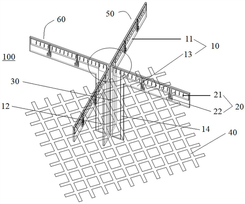
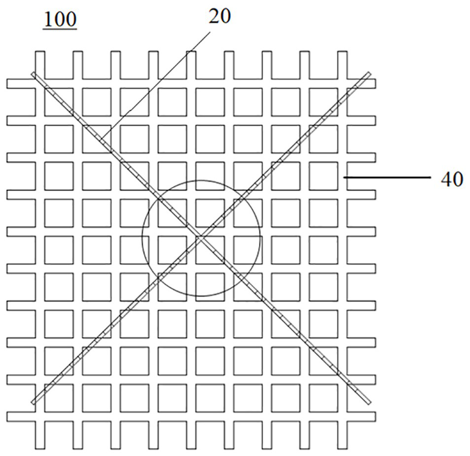
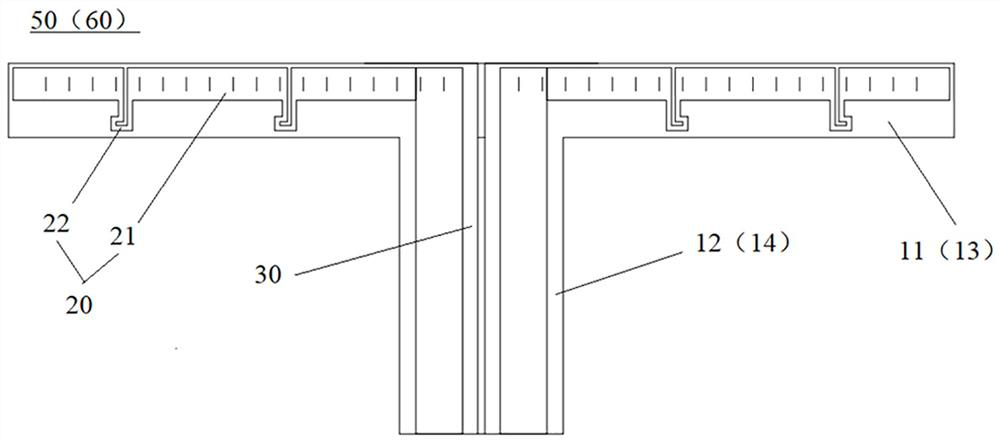
The invention provides a low-frequency radiation unit, including a dielectric substrate, a radiator, a feeding balun and a frequency selective surface structure; the radiating body is arranged on the dielectric substrate, the dielectric substrate is arranged on the feeding balun, and the feeding balun Set on the structure of the frequency selective surface, the upper end of the feeding balun is electrically connected to the radiator, and the lower end is electrically connected to the structure of the frequency selective surface; the structure of the frequency selective surface constitutes an open circuit for high frequency signals, and constitutes ground for low frequency signals structure. Thereby, the low-frequency radiation unit can effectively reduce the influence on the high-frequency radiation, and at the same time improve the flexibility of use; the present invention also provides a separable multi-frequency base station antenna, the reflection plate of which is provided with a plurality of high-frequency radiation A radiation unit and a plurality of the low-frequency radiation units; the frequency-selective surface structure of the low-frequency radiation unit is detachably connected to the reflector and located above the high-frequency radiation unit, so that the low-frequency radiation unit and the high-frequency radiation unit can be respectively Work independently.

Description

technical field [0001] The invention relates to the technical field of base station antennas for wireless communication, in particular to a low-frequency radiation unit and a detachable multi-frequency base station antenna. Background technique [0002] With the rapid development of mobile communication technology, the number of 5G base stations is increasing rapidly, and the problem of insufficient site resources is becoming increasingly apparent. For rapid deployment, 5G sites mainly add 5G antennas and equipment to the original 4G site resources, so multi-frequency base station antennas have become mainstream. Among them, the A+P base station antenna integrated with 4G and 5G (that is, active and passive integrated antenna) has more advantages in space size, wind load and management, and has a good development prospect, which is a trend in the future. [0003] The A+P base station antenna is a 4G and 5G integrated antenna, including an A (Active, active) antenna unit and...

Claims


Application Information

Patent Timeline
Patent Type & Authority Patents(China)
IPC IPC(8): H01Q1/38H01Q1/50H01Q21/00
CPCH01Q1/38H01Q1/50H01Q21/0006
Inventor 曾志邱小凯吴祖德刘维卓徐存伟吴倩
Owner MOBI TECH SHENZHEN CO LTD
Learn More