Ejection assembly of cleaning device and cleaning device

A cleaning device and component technology, which is applied in the direction of cleaning filter devices, cleaning equipment, vacuum cleaners, etc., can solve problems such as flying dust, and achieve the effect of avoiding flying dust and ingenious structural design

Active Publication Date: 2021-04-06
DREAM INNOVATION TECH (SUZHOU) CO LTD
View PDF7 Cites 2 Cited by
  • Summary
  • Abstract
  • Description
  • Claims
  • Application Information

AI Technical Summary

Problems solved by technology

In common hand-held vacuum cleaners, the dust collector or dust cup needs to be opened manually, which is extremely easy to cause dust to fly during the opening process

Method used


Image

  • Ejection assembly of cleaning device and cleaning device
  • Ejection assembly of cleaning device and cleaning device
  • Ejection assembly of cleaning device and cleaning device

Examples


Embodiment 1

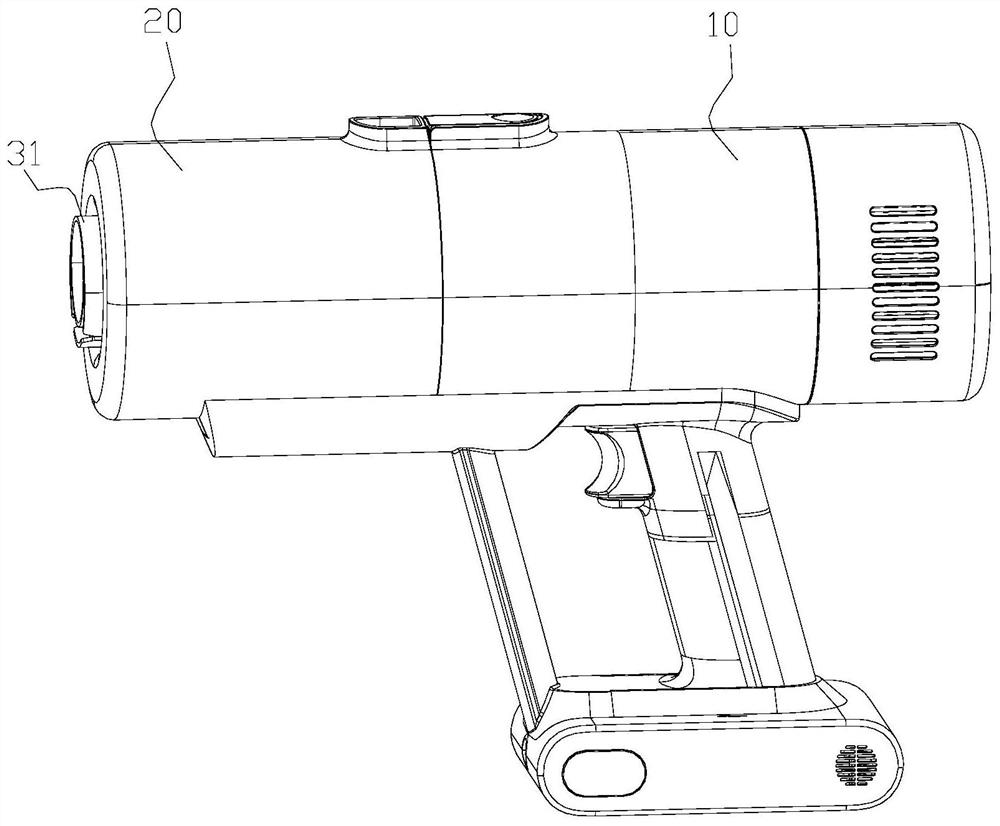
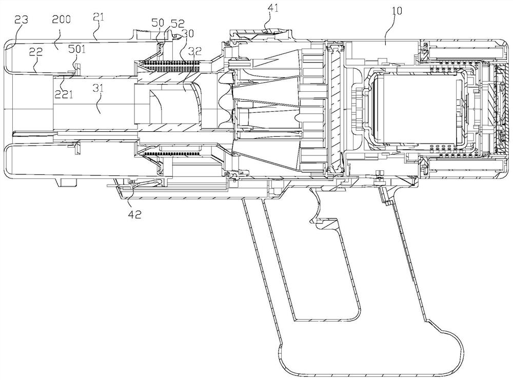
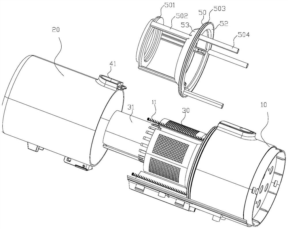
[0033]referenceFigure 1 - Figure 6 The ejection assembly of a cleaning device includes an elastic member 11, a ring member 50.

[0034]The elastic member 11 is mounted in the main body portion 10 of the cleaning device, the elastic member 11 is a compression spring, and when the dust cup 20 is mounted on the main body portion 10, the elastic member 11 is in a compressed state. The annular member 50 is provided with a guide post 504, and the elastic member 11 elongates in the axial direction of the guide post 504 to eject the ring member 50. The dust cup 20 is in contact with the annular member 50, and the elastic member 11 is released after the release ring 50 is moved and the abutting dust cup 20 is bounted to the detachable position. The annular member 50 is provided with a sterling portion 53, and the surface of the elastic member 11 can be automatically scratched simultaneously.

[0035]The cleaning device includes a main body portion 10, an intake conduit 31, a rotating conduit 32, a...

Embodiment 2

[0058]referenceFigure 7 - Figure 10 , A cleaning device of the ejection module includes an elastic member 11, a ring member 50, and a dust cup 20.

[0059]The elastic member 11 is mounted in the main body portion 10 of the cleaning device, the elastic member 11 is a compression spring, and when the dust cup 20 is mounted on the main body portion 10, the elastic member 11 is in a compressed state. The inner portion of the annular member 50 is provided with a guide post 504, and the elastic member 11 elongates in the axial direction of the guide post 504 to eject the ring member 50. The dust cup 20 is in contact with the annular member 50, and the elastic member 11 is released after ejection of the annular member 50 and pushes the implantable dust cup 20 to the detachable position. . The annular member 50 is provided with a sterling portion 53, and the surface of the elastic member 11 can be automatically scratched simultaneously.

[0060]The cleaning device includes a main body portion 10 ...


PUM


Abstract

The invention provides an ejection assembly of a cleaning device. The ejection assembly comprises an elastic piece installed on a main body part; an annular piece which is provided with a guide column, wherein the elastic piece can extend in the axial direction of the guide column so as to eject the annular piece; a dust cup which abuts against the annular piece, wherein the annular piece moves under the ejection effect of the elastic piece and pushes the abutting dust cup to move. The ejection assembly pushes the dust cup to move while ejecting the annular piece, the dust cup is ejected out by a certain distance, the dust cup is convenient to detach, and automatic dust scraping can be achieved while the dust cup is ejected out; the structural design of the annular piece is ingenious, and ejection and dust scraping of the dust cup are achieved under the condition that the diameter of the cleaning device is not increased; and a sealing piece is mounted on the annular piece, so that a first-stage dust area in the dust cup can be always in a sealed state in the process of ejecting the dust cup, and the influence on the user experience and the dust collection effect due to dust flying is reduced or avoided. The invention further provides a cleaning device.

Description

[Technical field][0001]The present invention relates to the field of cleaning devices, and more particularly to the echo assembly and cleaning device of a cleaning device.【Background technique】[0002]Conventional vacuum cleaners utilize the motor to generate air negative pressure in the sealed housing, inhalation of dust containing dust under differential pressure. In a common hand-held vacuum cleaner, the puma or dust cup needs to be opened manually, which is extremely easy to cause dust in the open process. Therefore, it is necessary to improve the prior art to overcome the defects in the prior art.[Summary][0003]It is an object of the present invention to provide a cleaning device ejection assembly and a cleaning device to solve the defects present in the background.[0004]It is an object of the present invention to achieve the following technical solutions:[0005]A cleaning device ejection module, including:[0006]Elastic member mounted on the main body;[0007]An annular member of a ...

Claims


Application Information

Patent Timeline
Patent Type & Authority Applications(China)
IPC IPC(8): A47L5/24A47L9/00A47L9/12A47L9/14A47L9/20
CPCA47L5/24A47L9/127A47L9/20A47L9/1409A47L9/00Y02A50/2351
Inventor 范苏湘杨文博冯勇兵
Owner DREAM INNOVATION TECH (SUZHOU) CO LTD
Why Eureka
Try Eureka