A kind of bone tap with anti-slip wire and using method thereof

A technology of anti-slip wire and tap, which is applied in the direction of bone drill guidance, medical science, surgery, etc. It can solve the problems of affecting the installation of medical components, useless drilling, and accurate control of the depth of tap rotation, so as to avoid rotational friction and facilitate control Effect

Active Publication Date: 2022-04-29
东莞市金名医疗器械有限公司
View PDF8 Cites 0 Cited by
  • Summary
  • Abstract
  • Description
  • Claims
  • Application Information

AI Technical Summary

Problems solved by technology

[0006] In order to solve the problems raised in the above-mentioned background technology, the present invention provides a bone tap with anti-slip wire and its use method, which solves the problem that the depth of the tap hole cannot be accurately controlled, and adding a part of the smooth guide part will cause There is no thread inside the drill hole, and there is a phenomenon that some drill holes are useless, which affects the subsequent installation of related medical components, and at the same time causes the problem of external damage to the patient's bone

Method used


Image

  • A kind of bone tap with anti-slip wire and using method thereof
  • A kind of bone tap with anti-slip wire and using method thereof
  • A kind of bone tap with anti-slip wire and using method thereof

Examples


Embodiment 1

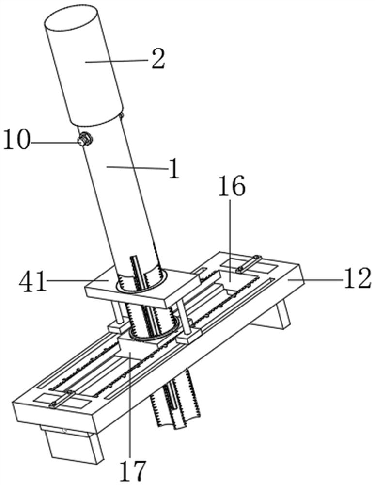
[0041] see figure 1 , figure 2 , image 3 , Figure 4 and Figure 5 As shown, the present invention provides the following technical solutions:

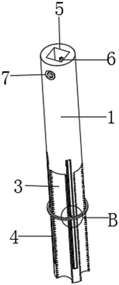
[0042] Such as figure 1 and figure 2 As shown, a bone tap with an anti-slip wire includes a tap 1, a bone drill rod 2 and an anti-slip positioning assembly. tapping thread 4,

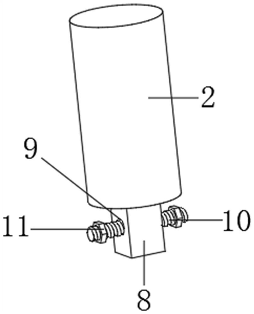
[0043] Such as figure 2 and image 3 As shown, the top end of the tap 1 and the bottom end of the bone drill rod 2 are provided with a mounting assembly, the mounting assembly includes a mounting groove 5, a connecting screw hole 6, an auxiliary gasket 7, a mounting block 8, a through screw hole 9, and a stud bolt 10 and auxiliary nut 11,

[0044] Specifically, the installation groove 5 is set at the center of the top of the tap 1, the connecting screw hole 6 is arranged at the center of the two opposite inner walls of the installation groove 5 and runs through the tap 1, and the auxiliary gasket 7 is fixed on the side wall of the tap 1 at the end...

Embodiment 2

[0053] On the basis of Example 1, refer to Figure 7 , Figure 8 and Figure 9 As shown, a bone tap with non-slip wire:

[0054] A depth control assembly is arranged on the side wall of the screw tap 1, and the depth control assembly includes a vertical chute 27, a vertical slider 28, an electromagnet rod 29, a limit ring 30, an indicator scale 31, a transition ring groove 32, a spring 33 and a transition ring 34 ,

[0055] Specifically, the vertical chute 27 is arranged on the side wall of the tap 1, the vertical slider 28 slides in the vertical chute 27, the electromagnet rod 29 is fixed between the two ends of the vertical chute 27, and the electromagnet rod 29 moves through the vertical slider 28. , the limit ring 30 is fixed on the side of the vertical slider 28, the indicating scale 31 is arranged on the edge of the vertical chute 27, the transition ring groove 32 is opened in the center of the top end of the positioning slider 17, the spring 33 is fixed in the center...

Embodiment 3

[0061] On the basis of Example 2, refer to Figure 5 , Figure 6 and Figure 10 As shown, a bone tap with anti-slip wire: connecting grooves 22 are symmetrically opened on both sides of the center of the top of the positioning bar 12, the expansion plate 13 is installed in the connecting groove 22, and the top of the positioning bar 12 is symmetrical with the connecting groove 22 Two sets of positioning screw holes 23 are symmetrically arranged, and a positioning plate 24 is fixed at the center of the top of the telescopic plate 13. The positioning plate 24 is provided with a matching screw hole 25 that cooperates with the positioning screw hole 23, and the internal thread of the matching screw hole 25 and the positioning screw hole 23 Positioning screws 26 are connected, and auxiliary positioning components are also arranged on the positioning bar 12. The auxiliary positioning components include auxiliary chute 35, auxiliary slider 36, connecting block 37, connecting hole 38...


PUM


Abstract

The invention belongs to the technical field of bone taps, in particular to a bone tap with anti-slip wires, including a tap, a bone drill rod and an anti-slip positioning assembly. Anti-slip tapping threads are provided, and the top end of the tap and the bottom end of the bone drill rod are provided with installation components. The installation components include installation grooves, connecting screw holes, auxiliary gaskets, installation blocks, through screw holes, stud bolts and auxiliary nuts. The anti-slip positioning assembly includes positioning bars, telescopic plates, piston plates, adjustment buttons, positioning chute, positioning sliders, positioning scales, scale indicator strips, positioning holes and electromagnet plates, and depth control components are arranged on the side wall of the tap. The depth control assembly includes a vertical chute, a vertical slider, an electromagnet rod, a limit ring, an indicator scale, a transition ring groove, a spring and a transition ring.

Description

technical field [0001] The invention belongs to the technical field of bone taps, and in particular relates to a bone tap with anti-slip wires and a use method thereof. Background technique [0002] During the treatment of clinical patients in orthopedic surgery or neurosurgery, it is often necessary to use bone plates and bone screws to fix and repair bone trauma. Among them, some parts of the bone need to be pre-drilled and manually tapped before the screws can be smoothly screwed in. Especially in neurosurgery, due to the natural inhomogeneity of the density and thickness of the human skull, there is a slight difference in surgical tapping. If you are not careful, it is easy to damage the pre-drilled hole or even injure the meninges and nerve tissue, and there is a risk of causing great harm to the patient. Therefore, there are very high requirements for the depth and direction of the tapping. At the same time, the existing bone screw part is made of non-metallic materia...

Claims


Application Information

Patent Timeline
Patent Type & Authority Patents(China)
IPC IPC(8): A61B17/16A61B17/17
CPCA61B17/1655A61B17/162A61B17/17
Inventor 张晓春
Owner 东莞市金名医疗器械有限公司
Why Eureka
Try Eureka